
User`s manual


SECTION 5: DS2100 FUNCTIONAL OVERVIEW
DS2100 User's Manual
C27750-001
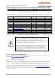
0x60F6/6 current_loop_foldback_breakpoint f32 Amp calimin
Table 5.29 List of Current Loop Compensator Gains
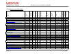
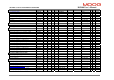
The table below lists parameter or signals that can be monitored by the GUI, and can be useful during loop tuning.
Index Name Type Units Comment
0x60F7/4 current_d-axis_observer f32 Amps id
0x60F7/5 current_q-axis_observer f32 Amps iq
0x60F7/6 current_d-axis_demand f32 Amps idd
0x60F7/7 current_q-axis_demand f32 Amps iqd
0x2410/13 current_phase_A_demand s16 Amps iad
0x2410/14 current_phase_B_demand s16 Amps ibd
0x2210/ 14 current_phase_A_feedback s16 see note 1 dspias
0x2210/ 15 current_phase_B_feedback s16 see note 1 dspibs
0x60F6/6 current_loop_q-axis_error f32 Amps qcomp.error
0x60F6/7 current_loop_d-axis_error f32 Amps dcomp.error
0x60F6/13 current_loop_alpha_observer_error f32 Amps oacomp.error
0x60F6/14 current_loop_beta_observer_error f32 Amps obcomp.error
0x60F7/9 current_actual f32 Amps iqact
Table 5.30 List of Current Loop Signal Parameters
5.11.3.2 Motor Velocity Loop Sample Rate
The motor velocity loop sample period can be set to any multiple of the current loop sample period (~100us) using
the parameter motor_velocity_loop_rate_divider
(0x60F6/15).
5.11.3.3 Motor Velocity feedback filter
A low-pass first order filter is also included on the motor feedback velocity. The motor feedback velocity is held in
the parameter motor_velocity_actual (0x60F6/16), with the low-pass filtered velocity held in a parameter called
motor_velocity_filtered (0x60F6/18). It is this filtered velocity variable that is used to limit the motor velocity.
The filter is a simple Euler approximation filter, characterised by two filter coefficients. The filter cut-off is
specified with a filter cut-off factor (FCF), held in a parameter called motor_velocity_filter_cutoff_factor
(0x60F6/17). The two filter coefficients (a
1
and b
0
) are computed in the embedded software each time the user
writes to the cut-off factor
WARNING - DANGER OF UNCONTROLLED MOTOR ACCELERATION
The DS2100 has specialised motor current compensation. For optimum
p
erformance the DS2100 operates a software model of the current loop. The correct
motor electrical parameters are required for this software model. Large errors in the
motor parameters can result in uncontrolled motion.
Small torque commands can result in a continuous motor acceleration. The velocity
of the motor can increase in an uncontrolled way if no counter-balancing torque is
present. The user's control system should ensure that the speed of the motor is
monitored, and that a compensating torque command is applied to control the motor
s
p
eed if necessar
y
.