
User`s manual


SECTION 5: DS2100 FUNCTIONAL OVERVIEW
DS2100 User's Manual
C27750-001
5.11.3 Current / Torque Loop Compensator
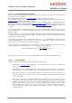
The inner most loop is the current or torque loop. The current loop tuning gains are computed from a Matlab
simulation. This uses time domain continuous time analysis to compute the Laplace domain gains for the current
controller. These are then mapped to the discrete domain using a standard pole placement algorithm. A default set
of current loop parameters will be held in the GUI motor database for all standard motors. The general current loop
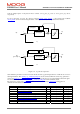
control structure, along with parameter names are illustrated below. The parameters indicated are accessible to the
user, and can be plotted on the GUI oscilloscope if required.
PMSM
3 Phase
inverter
Clarke
Transformation
αβ
abc
dspias
Park
Transformation
i
αβ
αβ
dq
Inverse Park
Transformation
Space
Vector
Modulation
*
V
αβ
PI
iqd
vcq
+
-
id
θ,
ω
αβ
dq
^
i
αβ
vwd
vq
State
Observer
State
Feedback
Decoupling
idd
(= 0)
vcd
vd
iq
dspibs
vwq
veq
+
+
iqact
αβ
dq
Clarke/Park
Invers e
θ
iad (sinusoidal phase A demand)
ibd (sinusoidal phase B demand)
Figure 5.10 : General Current Loop Structure
5.11.3.1 Current Loop Components
The current control consists of a pair of compensators, one for the q-axis current control, and the other for d-axis
current control. The feedback currents current_q-axis_observer
and current_d-axis_observer are output from the
predictive current state observers. The predictive observer is used by default for improved performance, by setting
the OBSERVER bit in the mode request of the drive. The actual q-axis current current_actual
, is computed directly