
User`s manual


SECTION 5: DS2100 FUNCTIONAL OVERVIEW
DS2100 User's Manual
C27750-001
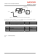
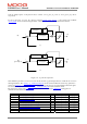
If velocity_loop_filter_mode is set to 2, then all 9 parameters are used to compute the filter output. This
configuration is consistent with a second order band-pass or band-stop butterworth digital filter.
Naturally, lower order filter designs are allowed. For example, a first order filter. But in this case the unused
parameter must be set to zero.
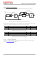
5.11.2.4.1 Low-pass filter
For example the coefficients of a second order low-pass butterworth filter with a cut-off frequency of 0.1 time’s half
the sampling frequency, can be determined as being: -
b
0
.. b
2
= 0.02008336556421 0.04016673112842 0.02008336556421
a
0
.. a
2
= 1.00000000000000 -1.56101807580072 0.64135153805756
If the velocity loop rate modulus is 4 and the switching frequency parameter is 9920Hz, Then, the velocity loop
sample rate is 400 μs approximately (= 2.5KHz approx).
Hence, the 0.1 filter factor means that the low-pass filter cut-off is 0.1*(Fs / 2) = 0.1*(2.5KHz / 2) = 125Hz.
Setting the filter coefficient parameters of the filter accordingly and setting the mode to 1, will implement this filter,
in the drive. Note that parameter a0 is always 1.0.
5.11.2.4.2 Band-stop filter (Notch)
The coefficients of a second order band-stop butterworth filter with a notch between 0.1 time’s half the sampling
frequency, and 0.2 time’s half the sampling frequency, can be determined as being: -
b
0
.. b
4
= 0.80059240346457 -2.88889936383274 4.20729857288451
-2.88889936383274 0.80059240346457
a
0
.. a
4
= 1.00000000000000 -3.21244081546948 4.16713184175608
-2.56535791219600 0.64135153805756
If the velocity loop rate modulus is 4 and the switching frequency parameter is 9920Hz, Then, the velocity loop
sample rate is 400 μs approximately (= 2.5KHz approx).
Hence, the notch entry cut-off is: - 0.1*(Fs / 2) = 0.1*(2.5KHz / 2) = 125Hz.
And, the notch exit cut-off is: - 0.2*(Fs / 2) = 0.2*(2.5KHz / 2) = 250Hz.
Setting the filter coefficient parameters of the filter accordingly and setting the mode to 2, will implement this filter,
in the drive. Note that parameter a0 is always 1.0.
5.11.2.5 Velocity feedback filter
A low-pass first order filter is also included on the motor feedback velocity. The feedback velocity is held in the
parameter velocity_actual (0x6510/10), with the low-pass filtered velocity held in a parameter called
velocity_filtered (0x6510/15). It is this filtered velocity variable that is used to close the velocity loop.