
User`s manual


DS2100 User's Manual SECTION 5: DS2100 FUNCTIONAL OVERVIEW
PAGE 5-48
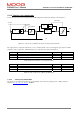
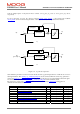
Velocity Limit
torque
100%
actual velocity
1.05 * Velocity Limit
5 %
Automatic or Manual
Mode Limit
Figure 5.9 : Velocity limiting when in Torque Mode
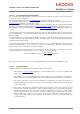
5.11.2.4 Velocity Loop Filter
The generic filter has 9 programmable parameters. Therefore, it may be configured as hi-pass, low-pass, band-pass
or band-stop, to allow for maximum flexibility. The output of the velocity compensator becomes the input to the
generic filter, denoted by current_demand_velocity_comp_output. The output of the generic filter is
current_demand_generic_filter_output (0x60F7/11). These two parameters may be monitored on the GUI scope to
view the filter activity in real time. The filter may be included/excluded by setting/clearing the appropriate bit in the
control loop configuration (see section 5.11.4)
NOTE
: The default filter operating period is velocity_loop_rate_divider / switching_frequency = 4/9920 = (approx
400 μs).
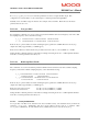
The Generic filter that is implemented is listed below, where
)(kyf is the filter output, and )(ky is the filter input
at a particular sample instant k.
()
()
)4()3()2()1()(
)4()3()2()1()(
43210
4321
−×+−×+−×+−×+×
+
−
×
+
−
×
+
−×
+
−×−=
kybkybkybkybkyb
kyfakyfakyfakyfakyf
The filter has the following set of parameters: -
Index Name Type
0x25C1/ 1 velocity_loop_filter_coefficient_a1 F32
0x25C1/ 2 velocity_loop_filter_coefficient_a2 F32
0x25C1/ 3 velocity_loop_filter_coefficient_a3 F32
0x25C1/ 4 velocity_loop_filter_coefficient_a4 F32
0x25C1/ 5 velocity_loop_filter_coefficient_b0 F32
0x25C1/ 6 velocity_loop_filter_coefficient_b1 F32
0x25C1/ 7 velocity_loop_filter_coefficient_b2 F32
0x25C1/ 8 velocity_loop_filter_coefficient_b3 F32
0x25C1/ 9 velocity_loop_filter_coefficient_b4 F32
0x25C1/
10
velocity_loop_mode F32
Table 5.28 List of Filter Parameters
The mode parameter determines the number of multiplications used to compute the filter output. If
velocity_loop_filter_mode is set to 1, then only parameters b0, b1, b2, a1, a2 are used to compute the filter output.
This configuration is consistent with a second order low-pass or high-pass butterworth digital filter.