
User`s manual


DS2100 User's Manual SECTION 5: DS2100 FUNCTIONAL OVERVIEW
PAGE 5-44
In addition, if the absolute value of the position error of the axis is smaller than a programmable limit
(position_TO_enable_velocity_integrator), then the I part of the velocity compensator, used when in position mode,
must be enabled to overcome friction i.e.: -
Abs(position error) <= limit => Activate the I-Term in the velocity compensator.
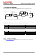
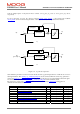
The compensator has a structure as shown below.
pos
+
-
thermal limit
factor
Ka
abs(in*) <
Ka
Kp
2
yes
no
en
in
* in rad
motvelliminc
-motvelliminc
en
in
sgn(in)*
2*Ka*(abs(in) - )
Ka
2* Kp
2
vcmd
motvelliminc
-motvelliminc
vcmd
Figure 5.6 : Position Loop Time Optimal Compensator Structure
The time-optimal position compensator has gains as listed below.
Index Name Type Units
0x60FB/6 position_TO_loop_a-gain f32 rad/s
2
0x60FB/7 position_TO_loop _p-gain f32 1/s
0x60FB/8 position_TO_loop _enable_velocity_i-term f32 rad
Table 5.22 List of Position Loop Time Optimal Compensator Gains
Index Name Type Units
0x60FB/5 position_TO_loop _error f32 increments
0x6510/3 internal_loop_demand f32 increments.
0x6510/13 velocity_command_acceleration_limited f32 incs/Tsamp
Table 5.23 Position Loop TO Compensator Read-only Parameters
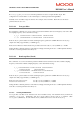
5.11.1.3 Velocity compensator (when in position mode)
When in position mode, the position compensator output is a velocity command, which is input to a PI velocity
compensator, to produce the torque demand. Note that the velocity compensator used in position mode is separate to
that used in velocity mode, thus allowing different gains to be used in velocity mode to position mode. The PI
velocity loop compensator structure is shown below, where vcmdsav is the acceleration limited velocity command,
in incs/Tsamp. Velf is the filtered actual velocity, and iqdv is the compensator output, or torque command.: -