
User`s manual


SECTION 5: DS2100 FUNCTIONAL OVERVIEW
DS2100 User's Manual
C27750-001
5.11.1 Position Loop Compensator
5.11.1.1 PI Compensator
The outer most loop is the position loop. Two options exist for the position compensator. These are a PI
compensator; or a Time-optimal compensator.
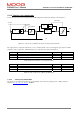
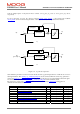
The PI compensator has a structure as shown in the diagram below: -
Ki
1
s
pos
demand
+
-
motvelliminc
-motvelliminc
vcmd
Anti-Windup
Kp
Figure 5.5 : Position Loop PI Compensator Structure
The output of the compensator is limited to motvelliminc, a term derived from the motor_max_velocity (0x6410/10)
parameter. The compensator also implements anti-windup for the compensator’s integrator. The PI compensator
has the gains as listed below.
Index Name Type Units
0x60FB/2 position_PI_loop_p-gain f32 1/s
0x60FB/3 position_PI_ loop_i-gain f32 1/s
2
Table 5.20 List of Position Loop PI Compensator Gains
Index Name Type Units
0x60FB/4 position_PI_loop_error f32 increments
0x6510/3 internal_loop_demand f32 increments.
0x6510/13 velocity_command_acceleration_limited f32 incs/Tsamp
Table 5.21 Position Loop PI Compensator Read-only Parameters
5.11.1.2 Time-Optimal Compensator
The time-optimal compensator is a non-linear compensator that uses a square root function of the position error, to
give optimal deceleration performance.
The position error is scaled by parameter thermal_limit_factor (0x280A 1) to give a scaled position error (i.e.
thermal_limit_factor is 1 when no limiting, <1 when limiting),. Dependent on the size (i.e. absolute) of this scaled
position error, the output of the compensator will have a linear relationship to the scaled position error, for small
position errors, OR will have a square root relationship for larger errors. The cut-off point between the linear and
square root relationship depends on Ka / (Kp
2
).