
User`s manual


DS2100 User's Manual SECTION 5: DS2100 FUNCTIONAL OVERVIEW
PAGE 5-38
5.10.1.2 Digital Input Debounce Count
The count for all digital input is by default set to 1. The digital inputs are checked at a fixed rate (every 2ms). By
setting the count to a higher value, the handler function will only be called, when the input is seen to have settled at
a level, for the defined number of counts, each time it is checked.
5.10.1.3 Digital Input Invert Input
This parameter invert the logic associated with a digital input handler function. Default operation for each handler
function was listed earlier. If the invert option is set, it will invert this logic. By default the invert option is not set.
For example, the default operation of the automatic/manual input is to set the drive into manual mode if the input is
cleared, and into automatic mode if the input is set. By setting the invert parameter for this input, it will set the drive
into automatic mode if the input is cleared, and into manual mode if the input is set.
5.10.1.4 Digital Input Status Word
The digital input status word shows the state of the 8 bits of the digital input word. The LSB corresponds to I1, and
the MSB corresponds to I8. A bit is shown as 1, if the digital input is set, and shown as 0, if the digital input is
cleared. This is the case regardless of the invert option being set.
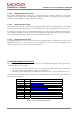
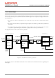
5.10.2 Digital Output Functionality
There are 3 digital outputs on the DS2100, numbered O1 to O3 on the DS2100 front-panel. All 3 outputs are user-
configurable. The user can configure: -
• The bits within a specific parameter that is to be associated with the digital output. This is performed by
setting the parameter field number and a mask to select specific bits.
• Invert the logic of the digital output, such that if the selected bit is set, the output is cleared and vice versa.
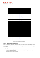
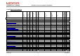
The parameters associated with outputs are listed below. Note that the names of the parameters, and the numbers on
the front-panel both start at 1: -
Index Type Name
0x2C2C/1 U16 digital_output_1_field_number
0x2C2C/2 U32 digital_output_1_mask
0x2C2C/3 U08 digital_output_1_invert
0x2C2C/4 U16 digital_output_2_field_number
0x2C2C/5 U32 digital_output_2_mask
0x2C2C/6 U08 digital_output_2_invert
0x2C2C/7 U16 digital_output_3_field_number
0x2C2C/8 U32 digital_output_3_mask
0x2C2C/9 U08 digital_output_3_invert
Table 5.18 List of Digital Output Parameters