
User`s manual


DS2100 User's Manual SECTION 5: DS2100 FUNCTIONAL OVERVIEW
PAGE 5-22
5.6 Encoder Input
The encoder input allows the connection of various incremental encoders for drive position feedback, velocity
feedback or for motor commutation (rotor angle feedback).
The encoder signals of an encoder with analogue sinusoidal output signals can be used for increased resolution
through angle interpolation within one optical increment.
Channel A
analogue
Channel B
analogue
Zero
Marker
Voltage
Angle
0
Angle
0
Count
Voltage
Angle
0
Channel A
digital
Channel B
digital
Level
Angle
0
1
Level
Angle
0
1
0123456-4 -3 -2 -1 ......
one optical
increment
Voltage
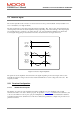
Figure 5.3: encoder signals
The picture shows typical analogue encoder signals and the digital signals derived from the analogue signals. The
direction of rotation shown is positive, so that channel B leads channel A. By counting every digital signal
transistion, the number of counts per mechanical revolution is four times the number of optical increments. Using
the analogue input signals the angle in between the increments can be interpolated to achieve much higher
resolution.
5.6.1 Encoder Configuration
5.6.1.1 Encoder Supply Voltage
The supply voltage of the encoder can be selected with the parameter encoder_supply
(index 0x2e20, subindex 1).
It has to be set first to ensure proper operation. The following values are valid for encoder_supply
:
5 - +5 Volts supply voltage
8 - +8 Volts supply voltage
12 - +12 Volts supply voltage
All other values will return an error when written.