
User`s manual


DS2100 User's Manual SECTION 5: DS2100 FUNCTIONAL OVERVIEW
PAGE 5-8 C27750-001
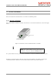
5.3.4 Low Voltage Control Power Supply
Control power for the logic circuits is generated by a DC/DC converter, which provides control-circuitry power that
is isolated from the mains input. This control voltage also powers the cooling fans. The DC/DC can generate
control power from two sources
1. D.C. Bus if it is greater than 120Vd.c. (Not available on the DS2100 μA size drives)
2. 24Vd.c. external supply which is provided by the user specially for control-backup power
These two sources are diode ‘ORed’ together to produce the internal 24V logic backup supply.
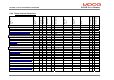
The state of the internal control electronics logic supplies are available to the user to monitor. If these supplies are
out of tolerance the drive will report a fault and react accordingly. The parameters associated with viewing the
internal logic supplies are given below.
Parameter Name Index / Subindex Description
supply_+24V 0x2810 / 25 Internal 24V Logic Supply
supply_+3V3 0x2810 / 5 3.3V Logic Supply
supply_-15V 0x2810 / 10 -15V Logic Supply
supply_+15V 0x2810 / 15 +15V Logic Supply
supply_+2V_ref 0x2810 / 20 2V Reference Level
encoder_supply 0x2810 / 30 Encoder Supply
Table 5.2 Logic Voltage Supply Monitoring Parameters
If the internal 24V logic supply voltage falls below 20V, the drive will disable and enter a fault status (F9). The
drive will automatically perform a power down save which saves certain data to memory such as elapsed time. This
save does not however save all parameters to non-volatile memory. Any unsaved parameters will be lost if the
internal 24V logic backup is lost.