
User`s manual


DS2100 User's Manual
SECTION 3: WIRING AND INSTALLATION
PAGE 3-60 C27750-001
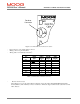
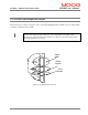
3.11.5 Motor Encoder Connection
The DS2100 encoder input supports a variety of encoders. These include Analogue, SSI, Hiperface and Endat. The
connections to the drive for each of these encoder types are given in Table 3.3-28.
Encoder
Connector
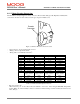
Figure 3.3.45 Motor Encoder Connector Location
-
Fixed connector: 15 pin, female Sub-D connector
-
Mating connector, 15pin male Sub-D
-
Wiring: cable. 28-18AWG (0.14-0.82mm
2
)
Encoder Type
Pos Analogue SSI Hiperface Endat
J4.1 Shield Shield Shield Shield
J4.2 - Sine - - Sine - Channel B
J4.3 - Cosine - - Cosine - Channel A
J4.4 Gnd Supply Gnd Supply Gnd Supply Gnd Supply
J4.5 - - Clock - - Clock
J4.6 - Channel Z (Zero) - Data RS485 - - Data
J4.7 - - - -
J4.8 NTC/PTC NTC/PTC NTC/PTC NTC/PTC
J4.9 + Sine - + Sine + Channel B
J4.10 + Cosine - + Cosine + Channel A
J4.11 +5 V .. +12V
Supply (150 mA
max.)
+5 V .. +12V
Supply (150 mA
max.)
+5 V .. +12V
Supply (150 mA
max.)
+5 V .. +12V
Supply (150 mA
max.)
J4.12 - Fault + Clock - + Clock
J4.13 + Channel Z (Zero)
+ Data RS485 + + Data
J4.14 Gnd Supply Gnd Supply Gnd Supply Gnd Supply
J4.15 NTC/PTC NTC/PTC NTC/PTC NTC/PTC
Table 3.3-28 Encoder Cable Input Connections
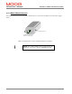
- Encoder Connector (J4)
“Motor Encoder port” for the “Motor Encoder Channels” and for the “Motor Integral NTC/PTC Temperature
Control (PIN 8-15). This Auxiliary-connector is referred to Limited Voltage / Current circuits (rated max 5.5 Vdc
±10%, 400 µA).