
User`s manual


DS2100 User's Manual
SECTION 3: WIRING AND INSTALLATION
PAGE 3-58 C27750-001
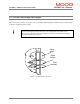
Resolver
Connector
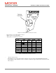
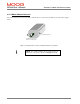
Figure 3.3.43 Motor Resolver Connector Location
- Fixed connector: 9 pin, female Sub-D connector
- Mating connector, 9 pin male Sub-D
- Wiring: cable. 28-18AWG (0.14-0.82mm
2
)
MOTOR RESOLVER CONNECTOR
Pos Signal
Type
FAS T/
FAS K
FAS N/
FAS Y
G4xx
(FASG)
J5.1
Cosϕ (S2)
C 1 3
J5.2
ϕ
Cos
(S4)
E 2 4
J5.9 V-Ref (R1) D 10 7
J5.7 0V (R2) B 7 8
J5.8 PTC\NTC N 8 6
J5.6 PTC\NTC A 9 5
J5.4
Sin
ϕ
(S1)
G 11 1
J5.5
ϕ
Sin
(S3)
H 12 2
J5.3 Shield S 3 -
Table 3.3-27 Resolver connections to motor
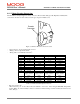
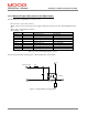
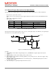
- Resolver Connector (J5)
“Motor Resolver port” for the “Motor Resolver Signals” and for the “Motor Integral NTC/PTC Temperature
Control (PIN 6-8). This Auxiliary-connector is referred to Limited Voltage / Current circuits (rated max 5.5 Vdc
±10%, 400 µA).