
Operating instructions


- 6 -
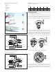
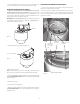
REATTACHING THE DOME ON PRESSURIZED UNITS
1. The dome on the pressurized unit must be attached correctly for the unit to function
properly. All screws and posts must line up exactly.
2. There are two posts on the underside of the dome which must be placed in the proper
slots on the housing (See Figure 13). One is located on the lanyard side of the dome and
the other is on the opposite side. The dome is oriented properly when the lanyard can
be attached to the housing.
Lanyard
Post (one on
either side)
Figure 13
Posts MUST t
in these slots
(one on either
side)
Close Up View of Dome
Lanyard screw hole
on housing
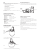
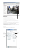
INSTALLING THE HOUSING ON THE BRACKET
1. Make sure that the (4) ange nuts on top of the DeputyDome™ are loosened
and that the tamper-resistant screws are not attached. Lift the unit up to the wall
mount and align the ange nuts with the keyhole slots on the mount (Figure 11). Turn
counterclockwise so that the nuts are inside the slots. Make sure that the holes for the
tamper-resistant screws line up. Tighten the ange nuts.
IMPORTANT NOTE: For non-pressurized units make sure the wiring on top of the housing
is fed through the opening on the bottom of the wall mount. On pressurized units the
connector will t directly into the opening.
Figure 11
Figure 12
1/4 - 20 Security Screws
3. Make all wiring connections.
NOTE: On non-pressurized versions be sure to cover the BNC connectors with electrical
tape to help prevent a short between the wall mount bracket and the video wiring.
4. Double check all wiring and push it back through the access opening into the wall mount
bracket. FOR PRESSURIZED HOUSINGS: At this point, pressurize the housing following the
instructions on page 7.
5. Reattach the access cover.
6. Test the function of all the equipment.
7. Reattach the lower dome with the tamper-resistant screws and security tool used earlier.
FOR PRESSURIZED HOUSINGS: See the important instructions on the next page for
reattaching the dome.
2. Reattach and tighten the (2) security screws (Figure 12).
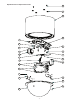
6. The liner should still be able to move up by about 1/16" on an inch to allow the liner
to move when shot and transfer the force to the housing instead of the pan/tilt.
Flange nuts