
Specifications

PRODUCT INSTRUCTIONS
INSTALLATION PREPARATION
1. Determine the mounting location. Be sure that you’ll be mounting
to a secure wall or ceiling, next to a stud.
2. Complete all wire and conduit runs prior to installation of the
housing.
R EVI S ION DATE: 02-02-2009
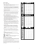
Depending on the voltage being used, refer to one of the formulas
below to select the correct power supply for cameras connected
in parallel (positive to positive, negative to negative):
Total current for a 12 V DC system:
TOTAL CURRENT = (350m A x total number of cameras)
Total current for a 24 VAC system:
TOTAL CURRENT = (202m A x total number of cameras)
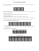
VOLTAGE CURRENT POWER
12 V DC 350m A 4.2W
24 VAC 202m A 4.8W
CABLE AND POWER G UIDELINE S
(Detailed info on Page 11)
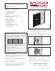
This chart shows the proper current needed for power supplies for
Warrior Series cameras. Use Class 2 Power only. Input voltage
must be between 12-28 VDC or 15-28 VAC.
81-I N5218 WARRIOR 5
WS 5
Cutout
S
T
U
D
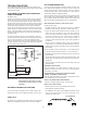
Figure 1
Figure 2
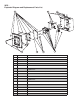
4. Position the double-gang box in the cutout against the stud and
mark the location of the two mounting holes on the side. Remove
the double-gang box.
5. Determine which side the conduit outlet will be located on: Top,
bottom, left, right, or back. Remove the desired conduit knock-
out.
CAUT ION : TO PREVENT DAMAGE, THE CAMERA AND
BRACKET MUST BE REMOVED BEFORE
TAKING OUT THE CONDUIT KNOCKOUT.
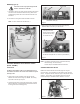
2. Using the security tool provided, loosen the (4) 8-32 security
fasteners and remove the face plate (Figure 2).
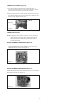
3. Loosen the (2) 8-32 screws holding the top of the camera bracket
and camera in place (Figure 3) and remove.
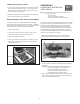
4 3/4"
4 3/4"
NOTE: The double-gang box must be flush with the drywall.
Two sets of mounting holes are provided on the
sides of the gang box. Use either to ensure that the
box is flush with the drywall.
Figure 3
INSTALLATION PROCEDURE
1. Cut a 4 3/4” x 4 3/4” square hole in the surface with one side
against the stud (Figure 1). If necessary, use the template
provided on the last page of these instructions.
TABLE OF CONT E NTS
Cable and Power Guidelines 1
Installation Preparation 1
Installation Procedure 1
Wiring 2
Optional Warrior Test Monitor Cable 2
Camera Bracket Setup 2
Camera Focusing 2
Camera S ettings 2
Completion of Installation 4
Window Guard™ Replacement 4
NVT Instructions 4
Warranty Information 6
Service and Safeguard Information 7
Troubleshooting 8
© 2009, Videolarm, Inc. All Rights Reserved