
Specifications

- 5 -
NOTE: This hi-res color camera uses a 1/4" chip and a 3-6mm
auto iris lens. It is comparable to a 1/3" chip using a
4-9mm auto iris lens.
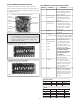
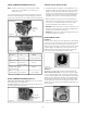
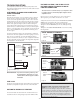
The operational settings are defi ned by four dip switches located on
the side of the PC Board (Figure 12 and 13). Moving the switches to
the UP position will activate specifi c settings. Refer to the chart below.
Figure 12
Auto Iris
Adjustment
Screw
Dip Switches
Figure 13
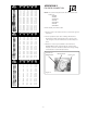
Dip Switch UP DOWN
1
(Iris) Auto Iris On Position for Fixed Lens
2
(Flickerless) Shutter speed Normal
fi xed at 1/100 sec.
3 (Back Light ON Normal
Compensation
4
(Synch Mode) Internal Synch Line Lock Mode
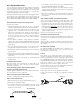
SERIAL NUMBERS BEGINNING WITH CB
SERIAL NUMBERS BEGINNING WITH CT
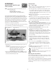
FIXED AND FIXED VARI-FOCAL LENSES. There are no user adjust-
able settings on these units (Figure 14)
AUTO IRIS LENSES: The auto iris can be adjusted if needed. See the
Troubleshooting section for instructions.
Figure 14
Auto Iris
adjustment
screw
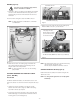
1. A cardboard template is included to test the adjustment of your
lens/bracket setup before reattaching the housing top. Place the
template over the lens/bracket set up, either on the back of the
housing or in opposing front plate screw holes depending on the
orientation of the setup. If the lens touches the cardboard the
setup WILL touch the dome or window. Readjust accordingly.
2. When the desired focus and location are achieved tighten the
thumb screws on the brackets in place using needle-nose pliers.
Use Loctite™ or an equivalent product to secure the screws,
especially in installations where vibration is a concern.
3. WARRIOR 2 - Adjust the inner liner so that the camera lens "sees"
through the opening. Replace the housing top and tightly fasten
the (4) security screws with the security tool.
WARRIOR 4 - Replace the housing top and tightly fasten the (4)
security screws with the security tool.
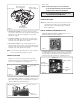
DOME/WINDOW CARE
WARRIOR 2
Handle the dome carefully to prevent scratching. If a scratch appears
over the lens you can turn the dome to move the scratch out of view.
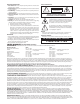
Remove the housing top as noted earlier. Loosen the (4) 10-32
Phillips head screws inside the top and turn the dome to the desired
orientation (Figure 15). Retighten the screws and replace the top,
making sure the inner liner opening lines up with the camera lens.
Clean the dome with an appropriate non-abrasive cleaner.
Figure 15
Figure 16
WARRIOR 4
The Warrior 4 is equipped with a scratch resistant window and a
Window Guard™ paint shield. The shield can be quickly changed
in cases of vandalism. Remove the housing top as directed earlier.
Loosen the (4) 8-32 Phillips head screws holding the window in place
and take out the window (Figure 16). Remove the vandalized paint
shield and replace it with a new one. Reattach the window, making
sure the paint shield is between the housing and the window, and
reattach the housing top. Clean the window with an appropriate non-
abrasive cleaner.
COMPLETION OF INSTALLATION