
Specifications
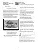

PRODUCT INSTRUCTIONS
INSTALLATION PREPARATION
1. Mount to a secure wall or ceiling. For outdoor application we also
recommend that the housing be mounted in a protected area.
2. Complete all wire and conduit runs prior to installation.
3. Determine the mounting method:
A. Mount directly to a wall or ceiling.
B. Mount to a standard 4-square electrical box (not provided).
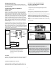
4. IMPORTANT REMINDER: For outdoor applications attach the
provided gasket to the back of the housing (Figure 1). WE
STRONGLY RECOMMEND USING A sealant. Place a light
bead of sealant around the perimeter of the gasket surface and
around the head of each screw.
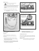
Conduit outlet
(Place on
bottom in
protected
outdoor
applications)
Figure 2
Mounting Holes
REVISION DATE: 11-09-2010
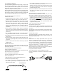
INSTALLATION PROCEDURE
1. Using the security tool provided, loosen the four security fasten-
ers and remove the housing top. NOTE: The housing top is held
to the base by a lanyard.
2. Determine which side the conduit outlet will be located on: Top,
bottom, left, or right.
NOTE: In protected outdoor applications place the conduit
outlet in the bottom position, facing the ground.
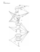
3. Position the housing in the desired location and mark the four
mounting holes (Figure 2).
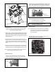
Figure 1
Set screw
4. Pull video and power wires through the desired conduit access
hole. Use the correct conduit plug to cover the unused hole.
NOTE: For outdoor applications use Teon™ tape on the
threads.
A. Use the 1/2" conduit plug to cover the 1/2"
threaded hole. Attach using a at head screwdriver.
B. Use the 3/4" conduit plug to cover the 3/4"
threaded
hole. To do this loosen the 6-32 set screw that
holds the connector in, remove the connector and
replace it with the plug. Once the plug is tightened
down, retighten the set screw.
NOTE: Make sure that the conduit plug and set screw are
securely tightened to help prevent tampering.
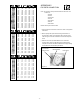
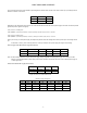
Depending on the voltage being used, refer to one of the formulas
below to select the correct power supply for cameras connected
in parallel (positive to positive, negative to negative):
Total current for a 12 VDC system:
TOTAL CURRENT = (350mA x total number of cameras)
Total current for a 24 VAC system:
TOTAL CURRENT = (202mA x total number of cameras)
VOLTAGE CURRENT POWER
12 VDC 350mA 4.2W
24 VAC 202mA 4.8W
CABLE AND POWER GUIDELINES
(Detailed info on Page 12)
This chart shows the proper current needed for power supplies for
Warrior Series cameras. Use Class 2 Power only. Input voltage
must be between 12-28 VDC or 15-28 VAC.
81-IN5217 WARRIOR 1 & 3
WS1(T/C) / WS3
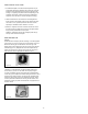
5. Attach the housing using #10 mounting screws, placing the
provided mounting pads against the head of the screw.
NOTE: When installing outdoors, remember to use sealant
around the screws and the back of the housing.
TABLE OF CONTENTS
Cable and Power Guidelines 1, 12
Installation Preparation 1
Installation Procedure 1
Wiring 2
Optional Warrior Test Monitor Cable 2
Camera Bracket Setup 2
Camera Focusing 3
Camera Settings 3
Completion of Installation 5
Dome/Window Care 5
NVT Instructions 6
IFS Instructions 7
Warranty Information 8
Service and Safeguard Information 9
Troubleshooting 10
Exploded View WS1 13
Replacement Parts List WS1 14
Exploded View WS3 15
Replacement Parts List WS3 16