
Operating instructions

- 3 -
23
22
21
20
19181716151413121110
987654321
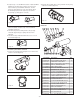
1. Insert the two mounting straps through the slots in the brackets
inside the sunshield (Figure 20).
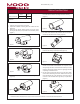
4. Complete steps 1-8 of the BMT10 instructions. Attach the BMT10
Tilt Bracket to the wall mount by using the (2) 3/8" hex head
bolts and washers pro vided with the wall mount. The wall
mount has (4) thread ed in serts for the hex head bolts at tach.
By al ter nating the pattern of the (2) bolts you can achieve
any pan angle you wish (Figures 17 and 18).
Part Number Description Qty.
1 90-BTSEC06 10-32X 5/8" BT HD SEC SCREW SS 6
2 92-WSTH04 #10 EXT TOOTH STAR L/W SS 14
3 30-VL1437 FRONT END PLATE, BMT10 1
4 96-GKBMT01 BMT10, FRONT END PLATE GASKET 1
5 96-GKBMT02 BMT10C, WINDOW GASKET 1
6 27-SHBMT10 BMT10 PAINT SHIELD 1
7 27-WDBMT10 BALLISTIC WINDOW FOR BMT10C 1
8 30-VL1439 WINDOW PLATE, BMT10C 1
9 90-BTRP32 10-32 X 1 3/8" PN HD PHIL SS 6
10 90-BTRP20 #10-32 X 3/8" PN HD PHIL SS 2
11 90-BTSC01 10-32 X 1/2 SOCKET CAP SCREW 1
12 30-VL1442 FRONT CAMERA PLATE, BMT10 1
13 30-VL1436 CAMERA SLED FOR BMT10C 1
14 90-BTHH04 1/4-20X1/2 RD HD SS 1
15 92-WSSL01 1/4 SPLIT LOCKWASHER 18-8 SS 1
16 90-BTSR17 #6-32 X 3/8" PN HD PHIL SS MS 1
17 72-HTP115 115VAC, 28 WATT HEATER 1
18 50-VL1435 BMT10C HOUSING BODY, SS 1
19 30-VL1494 BMT10 TILT BRACKET 1
20 94-FSSR02 BLK HEYCO STRAIN RELIEF #3224 2
21 92-WSSL02 5/16 SPLIT LOCKWASHER SS 4
22 90-BTHH33 5/16-18 X 3/4 HH SS 4
23 92-WSFN04 5/16" FLAT WASHER FOR BMT10 2
Figure 17
Figure 18
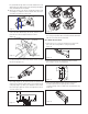
Figure 19
3. Fasten the two mounting straps securely around the housing us ing
a fl at-head screwdriver (Figure 22).
To Install the optional VLAY10 Sunshield
2. Align the sunshield (Figure 21).
PARTS LIST
Figure 20
Figure 21
Figure 22
5. After achiev ing the de sired pan angle, tighten down the (2)
3/8" hex head bolts. Complete steps 11-16 of the BMT10
In stallation in struc tions).
6. The wall mount packet assembly includes a 3/4" pipe plug.
Thread this plug into the pipe cou pling at the back of the
tilt bracket.
7. After the housing is installed the wall mount access cover can
be reinstalled (Figure 19).