
Operating instructions

- 2 -
2.00
4X .390Ø
.500
.500
1.500
2.000
5.500
1.000
2.000
Figure 9
Figure 16
Figure 10
Figure 11
Figure 12
Figure 13
Figure 14
Figure 15
PC Board
Power Wires
Video Connections
The (2) bolts with the large wash ers should be in stalled on the side
with the angled slot. Tilt the housing to the desired angle and tighten
all (4) of the tilt brack et hex head bolts.
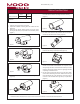
12. Attach your cam era to the cam era sled with the provided 1/4-20
screw (Figure 9). Adjust the camera so that the front of the lens is
even with the front tab of the cam era sled.
13. Con nect the in coming power wires to the hous ing PC board.
Connect the video cable directly to the camera, and run a set of
power wires from the housing PC board to the camera
(Figure 10).
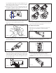
14. Once you have completed all of the wiring, make sure the wires go
over the back wall of the camera sled. Slide the camera sled back
into the housing (Figure 11).
15. The front ring of the camera sled should sit ap prox imately 2" inside
the housing ( Figure 12). The cam era sled can be ro tated to any
angle and secured in place, which allows you to mount the housing
at any angle (Figure 13). When you've rotated the camera sled to
the desired angle, tighten the camera sled ad justment screws to
secure the cam era sled.
16. Reattach the front end plate with the (6) tamper resistant screws and
the security tool provided. Make sure that the win dow and win dow
plate do not touch the cam era sled bracket.
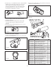
WALL MOUNT IN STRUC TIONS:
1. Remove the access cover by loosening the (2) security screws
at the front of the housing with the security tool provided
(Figure 14).
2. Mount the wall brack et to the wall with ap propri ate hard ware.
Refer to Figure 15 for the mount ing pattern.
3. Run all in coming wir ing through the hole in the back plate of
the wall mount bracket, then up through the hole in the
housing mount ing sur face (in be tween the (4) thread ed in serts)
(Figure 16).