
Operating instructions

-8 -
PRESETS - Allows the selection of the dwell times for each of the 64
presets. When this submenu is selected, the dwell time for each of
the 64 presets is displayed.
NOTE: If a preset has not been saved, the dwell time for that
preset will only be displayed as ".."
REMINDER: A dwell time of more than "0" can only be selected if
a preset has been saved.
Press "tilt up" or "tilt down" to select the desired preset.
Pan right and the dwell time selection will appear. Press "tilt up" or
"tilt down" to change the time.
Pan left to return to the Presets Selection sub-menu. Pan left
again to return to the Main Menu.
PATTERN: The MR7CS-9 allows recording of one pattern of up
to 128 seconds in length. This is a separate function from auto
tour.
TO RECORD A PATTERN:
Set preset 80 to begin recording.
Record your pattern.
Set preset 81 to stop recording.
TO RUN THE PATTERN:
Go to preset 80.
TO STOP THE PATTERN:
Move the joystick.
TO MAKE THE PATTERN PART OF AUTO TOUR:
Set a preset or presets for which you want the pattern
to run.
Go to the PRESETS section of the menu.
Go to the SET DWELL TIME function.
Set the dwell time for the desired presets to "0".
Exit the menu and go back to live video.
Press AUTO TOUR and the tour of each preset will begin. When
the tour reaches the preset designated for a dwell time of "0" the
pattern will run. The pattern can be set for as many presets as
desired, however, only one pattern can be recorded.
EXIT - Pan left to exit the Main Menu.
SYSTEM INFO - Displays the Pan Version, Tilt Version, Current Pan
Position and Current Tilt Position.
OTHER FEATURES:
Home Preset
3UHVHWLVWKH³KRPHSUHVHW´,IWKLVSUHVHWKDVEHHQGH¿QHGWKHQ
the VLTP385 will always go to this preset when the unit is powered
up.
Remote Address
The Address of the unit can be set by a remote command. This “soft”
address will be saved even if the unit loses power and will override
the dip switch set address. The “soft” address can be cleared by
a remote command and the address will be determined by the dip
switch setting.
Program Download
There are two software programs in the standard unit. Each program
can be updated via the command communication channel with a
laptop or other computer system.
Error Messages
The “COMM ERROR” message will be displayed at the top of the
screen whenever the MR7CS-9™ detects frame errors in the receive
data, such as when the RXA and RXB wires are reversed when using
RS485/422 or when the baud rate is incorrect.
The “CAMERA ERROR” message will be displayed at the top of the
screen whenever there is an error in communicating with the camera.
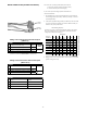
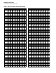
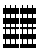
DIPSWITCH SETTINGS:
Address Dip switch settings, refer to Table 1 on next page.