
Operating instructions

-4 -
A
B
C
D
EF
G
H
R
J
K
L
MN
P
UT
S
NC
Alarm Common
Alarm In 3
Alarm In 2
Alarm In 1
RXB
TXB
TXA
Heater /Blower
Heater /Blower
Camera Power
Camera Power
Shield
Video
NC
RXA
NC
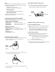
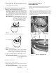
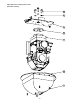
INSTALLING THE PAN/TILT
1. Slide the pan/tilt back into place. All of the electrical connections
are made by the edge connector and will be engaged at that point.
2. Place the pan/tilt inside the housing so that the alignment pins are
facing the housing PC board. The two vertical flanges on the pan/
tilt quick release plate should slide in between the two vertical
flanges on the housing plate. There are also notches on the back
side of the quick release plate that align with support tabs on the
housing plate (Figure 8).
Figure 8
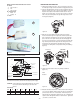
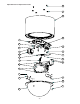
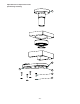
3. With the two vertical flanges lined up and the quick release
notches inserted through the support tabs, slide the pan/tilt side
ways, towards the housing PC board. There are two alignment
pins on the front of the quick release plate that will engage with
holes on the housing bracket. The pan/tilt should be pushed side-
ways until the panel fastener aligns with the mating insert in the
housing plate. Be gentle with the pan/tilt because the wiring
connections are being made as the pan/tilt is being slid sideways
(Figure 9).
Front View
Side View
Edge
Connector
Figure 10
Panel
Fastener
4. Tighten the panel fastener with a long Phillips screwdriver
(Figure 10).
Figure 9
5. Reattach the bullet-resistant liner. Make sure that the viewing slot
is in front of the ballistic window. Each liner arm has an alignment
pin that mates with a hole on the ballistic. When both pins are
aligned with their appropriate alignment hole, the (4) Phillips head
captive screws will align with inserts on the liner arms. Tighten the
(4) screws to secure the liner.
Wiring Chart Non-Pressurized Receiver Version
A. Heater
1) Red - Heater 1
2) N/C
3) Red - Heater
B. Camera Power
1) Black - V2
2) Orange - V1
C. RJ45
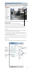
Wiring Pressurized Receiver Version
The following chart is provided as a general guide for the input power for
heater,blower and camera, between the housing and power supply.
CAUTION: Using smaller than recommended cable sizes can result
in poor performance and damage to the heater and
camera.
Figure 7
Figure 5
Wire Gauge
VA 22 20 18 16 14 12
70 25ft 40 ft 64 ft 100 ft 162 ft 260 ft
7 m 14 m 20 m 30 m 50 m 80 m
A
B
C