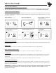
SIRIN CHEAT SHEET FREE EDITOR/LIBRARIAN Access and automate every parameter on and under the hood of your Sirin right from your DAW. Get the free Editor/Librarian software when you register your Sirin at Moogmusic.com/register STORE AND CHANGE PRESETS Up to 128 presets can be saved and loaded onto your Sirin using the free Editor/Librarian software. Sirin also supports MIDI Program Change messages, allowing almost any MIDI controller to change presets on your Sirin.
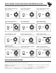
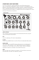
SHIFT PANEL FUNCTIONS QUICK REFERENCE GUIDE The GLIDE switch on your Sirin can act as a “shift” key, allowing quick access to a number of extended functions directly from the panel. MOD SOURCE SELECTION: HARD SYNC ON/OFF: VCO 2 MOD ONLY ON/OFF: GLIDE + LFO RATE GLIDE + VCO 2 LEVEL GLIDE + VCO LFO AMT VCO 2 BEAT FREQUENCY: EXT.
SIRIN
SIRIN MINITAUR Congratulations Congratulationson onyour yournew newAnalog Minitaur Synthesizer. Analog Bass Sirin, Synthesizer, the Analog a Messenger powerful, compact of Joy, isMoog a limited-edition synthesizersynthesizer with a classic module one knob madeper in celebration function design. of theAt Moog onlyHouse 8.5" x of 5.25" Electronicus and less than Pop-up 3lbs,experience.
IMPORTANT SAFETY INSTRUCTIONS PLEASE READ BEFORE USING THIS PRODUCT When using Sirin, these basic precautions should always be followed. 1. Read all the instructions before using this product. 2. Do not use Sirin near water. 3. This product, in combination with an amplifier and headphones or speakers, may be capable of producing sound levels that could cause permanent hearing loss. Do not operate for a long period of time at a high volume level or at a level that is uncomfortable.
CONTENTS THE BASICS Unpacking & Inspection••••••••••••••••••••• 4 Setup and Connections•••••••••••••••••••••• 4 Overviews and Features••••••••••••••••••••• 6 Signal Flow••••••••••••••••••••••••••••••••••• 8 Basic Operation•••••••••••••••••••••••••••••• 9 THE COMPONENTS Oscillators•••••••••••••••••••••••••••••••••••• 9 Glide•••••••••••••••••••••••••••••••••••••••••• 11 Mix•••••••••••••••••••••••••••••••••••••••••••• 11 Filter•••••••••••••••••••••••••••••••••••••••••• 12 Envelopes•••••••••••••••••••••
UNPACKING AND INSPECTION CHECK THE CONTENTS IN THE SHIPPING CARTON The Sirin is shipped with the following items: 1. Sirin Analog Synthesizer 2. A 12VDC Power Adaptor 3. A “Getting Started” guide 4. Registration Card WHAT YOU WILL NEED 1. A MIDI keyboard or MIDI controller 2. A MIDI cable 3. A USB cable to connect Sirin to a host computer (for USB MIDI) 4.
POWER UP Apply power to the Sirin and to your MIDI controller. CONNECT TO AMPLIFIER Set Sirin’s volume control to minimum before connecting to an amplifier, mixer, or headphones. Set the amplifier volume to a comfortable listening level, and then slowly bring up the volume on Sirin as you play a few notes. NOTE: Use caution when adjusting initial volume levels, especially if connected to a subwoofer.
OVERVIEW AND FEATURES Sirin is a monophonic Analog Synthesizer with a 100% analog audio path. It is based on the legendary Taurus I and Taurus 3 Synthesizers. Sirin features 2 ultra-stable voltage controlled oscillators, a genuine Moog low pass filter, 2 envelope generators and a modulation circuit. Sirin has a classic one knob per function design in a rugged performance package that is small enough to take with you anywhere.
BACK PANEL HEADPHONE OUT 1/8” Stereo Headphone Output. AUDIO OUT 1/4” Unbalanced Output. AUDIO IN External Audio Input for processing audio through the Mixer and Filter section of the Sirin. CONTROL INPUTS Analog control inputs for Pitch, Filter, Volume and Gate. Use control voltage or a Moog EP3 expression pedal to connect and control the Sirin with everything from Moogerfoogers to modular systems. MIDI DIN MIDI and USB MIDI offer complete control of Sirin’s sound engine.
SIGNAL FLOW To understand how the Sirin generates sound, take a look at the diagram below. It shows the flow of Audio, Control Voltage and Modulation signals in the Sirin. Heavy lines indicate audio signals, which flow from left to right. Lighter lines indicate Control Voltages (CV’s), which flow from the top and from the bottom. Dotted lines indicate Modulation routings.
BASIC OPERATION The Sirin responds to MIDI messages on both DIN and USB MIDI Inputs. In addition, Sirin’s knobs and switches transmit MIDI Control Change (CC) commands via MIDI USB, allowing parameter adjustments to be captured by any MIDI-recording device. Sirin has an LED MIDI indicator that indicates MIDI activity on either the DIN MIDI or USB MIIDI connector. To further extend the Sirin’s capabilities, there are additional parameters that can be accessed via MIDI control.
FINE TUNE: Adjusts the frequency of both VCOs by approximately +/-1 semitone. The FINE TUNE control does not transmit MIDI. MIDI ACCESSIBLE CONTROL VCO 2 BEAT (CC# 18): Selects the fine frequency offset for VCO 2. The adjustment range is +/- 50 cents. Default = 64. NOTE SYNC (CC# 81): When enabled, NOTE SYNC forces both oscillators to start at the same time, eliminating any phase differences at the start of each “Note On” command. This ensures energy is consistent at the start of each new note.
GLIDE GLIDE (AKA ‘portamento’) is a musical effect that makes smooth changes in pitch between notes. Sirin’s GLIDE RATE is adjustable from instantaneous to extremely long. PANEL CONTROLS FOR GLIDE GLIDE Switch (CC# 65): Enables/Disables the GLIDE function. GLIDE is on when the LED is on. GLIDE RATE (CC# 5): Sets the rate of GLIDE that occurs when the note controlling Sirin changes.
VCO 2 LVL (CC# 16): Sets the level of VCO 2. MIDI ACCESSIBLE CONTROL EXTERNAL INPUT LEVEL (CC# 27): Adjusts the External Audio Input level. By default, the level is set for unity gain, but the level can be adjusted up to 200% Default = 64. FILTER The FILTER is a classic Moog 24dB/ Octave Low-Pass Filter design with resonance.
EG AMOUNT (CC# 22): Determines how much the Filter Envelope Generator (EG) adds to or subtracts from the Filter Cutoff control setting. When the EG AMOUNT knob is set to positive (+), turn the FILTER CUTOFF knob left to hear the effect. When the EG AMOUNT knob is set to negative (-), turn the FILTER CUTOFF knob right to hear the effect. Note that if the Cutoff frequency is set very high, a positive EG Amount may have little or no noticeable effect, regardless of the setting.
ENVELOPES Release Sustain Decay Amplitude The EGs are started by a Gate or MIDI Note message. Once started, their shape in time is set by the ATTACK, DECAY/RELEASE, and SUSTAIN controls, as well as the Release switch and length of the Note played. Attack ENVELOPE GENERATORS (EGs) add motion to a sound after a note is played. The Sirin has two separate Minimoog style Envelope Generators that affect the brightness and loudness of the Sirin's sound by modulating the Filter Cutoff (VCF) and Volume (VCA).
note is released, the EG moves back to zero at the rate set by this control. The time ranges from 1 msec to 30 seconds. The Release segment of the Envelope is determined by the state of the RELEASE switch (ON/OFF). AMPLIFIER SUSTAIN (CC# 30): Sets the Amplifier EG level after the Decay and before the Release portion. A note must be held longer than both the Attack and Decay time to reach the Sustain level. The level is adjustable from 0 to 100%.
MODULATION (MOD) MODULATION is an important part in the creation of musically-expressive sounds. Sirin’s MODULATION section provides an LFO with adjustable RATE and AMOUNT controls for the oscillators (VCO) and the Filter (VCF). The Low Frequency Oscillator (LFO) is a signal used to move the pitch of VCOs and the Filter Cutoff up and down automatically. A LFO can be used to simulate vibrato, create wobbling filter sweeps, or make interesting synthesizer sounds.
VOLUME (VCA) The Sirin features a monophonic Audio Output and a Headphone Output; both outputs appear on the back panel. Both ouputs are adjusted simultaneously by the VOLUME control. PANEL CONTROL FOR VOLUME VOLUME: Adjusts the output of the Voltage Controlled Amplifier (VCA) and Headphone levels. Rotating the control fully clockwise produces the maximum output. Rotating the control fully counterclockwise silences the Sirin. The VOLUME control does not transmit or receive MIDI. This is a post VCA control.
INPUT/OUTPUT PANEL The back panel provides all of the input and output connections. In addition to AUDIO INPUT/OUTPUT jacks, there are CV and GATE inputs, connections for MIDI, and the Power Connector. The Sirin does not have a power switch. BACK PANEL 12VDC (POWER INPUT) A barrel connector that accepts a +12VDC, tip positive power input from the power adaptor, which accepts 100-240 VAC, 50-60Hz.
PERFORMANCE TIPS: • You can use the Sirin to process any audio signal simply by plugging into the AUDIO IN jack. To hear the external audio signal, you will need a MIDI NOTE ON message. To hear the external audio signal without issuing a MIDI NOTE ON message, apply +5V to the GATE jack. This will leave the Gate open, and the Amplifier Envelope will remain at its Sustain level until the Gate closes.
MIDI OPERATIONS MIDI CHANNEL Sirin sends and receives on a single MIDI channel. By default, the Sirin is set to MIDI Channel 1, but it can be set to any MIDI Channel (1-16). To change the MIDI Channel on the Sirin: 1. Connect your MIDI controller or DAW to the Sirin. 2. Adjust the controller (or DAW) to transmit the desired MIDI Channel. 3. On the Sirin; press and hold all four panel switches (VCO 1 Wave, VCO 2 Wave, GLIDE and RELEASE).
MIDI CONTROL CHANGE (CC) MESSAGES The tables on the following pages list all MIDI CC messages for the Sirin. Messages shown with an (M) indicate parameters which are only accessible via MIDI. Bolded values indicate the appropriate range for 7-bit messages (MSB). NOTES: • Sirin sends 7-bit MIDI CC messages for all parameters. It can receive either 7-bit or 14-bit values for the parameters controlled by knobs, but only 7-bit values for parameters controlled by switches.
SECTION CONTROL/ PARAMETER MOD(MODULATION) OSCILLATORS MIXER CC VALUE/RANGE 3(MSB) 35(LSB) 0-127 LFO VCO AMOUNT Adjusts the modulation amount to the VCOs 13(MSB) 45(LSB) 0-127 LFO VCF AMOUNT Adjusts the Modulation amount to the VCF 12(MSB) 44(LSB) 0-127 LFO MIDI SYNC (M) Enables or disables ability of LFO to sync with MIDI CLOCK messages 87 LFO SYNC CLOCK DIV (M) Sets the LFO synchronization clock divider 86 See table on page 24 LFO KEY TRIGGER Re-triggers the LFO to the start of the cyc
CONTROL (SEE NOTE 1) MOD KEYBD PITCH WHEEL WHEEL RESPONSE RESPONSE RESPONSE VOLUME ENVELOPES SECTION CONTROL/ PARAMETER FUNCTION CC VCF ATTACK Adjusts the filter envelope attack time.
MIDI CC VALUES FOR THE LFO CLOCK DIVIDER (CC# 86) TIME VALUE DIVISION VALUE 1/64 Note Triplet 1/64 T 122-127 1/32 Note Triplet 1/32 T 116-121 1/32 Note 1/32 110-115 1/16 Note Triplet 1/16 T 104-109 1/16 Note 1/16 98-103 1/8 Note Triplet 1/8 T 92-97 Dotted 1/16 Note 1/16 DOT 86-91 1/8 Note 1/8 80-85 1/4 Note Triplet 1/4 T 74-79 Dotted 1/8 Note 1/8 DOT 68-73 1/4 Note 1/4 61-67 1/2 Note Triplet 1/2 T 55-60 Dotted 1/4 Note Triplet 1/4 DOT 49-54 1/2 Note 1/2 43-48 Who
APPENDIX A - MIDI IMPLEMENTATION CHART FUNCTION TRANSMITTED RECOGNIZED REMARKS BASIC CHANNEL Default Changed 1 1-16 1 1-16 Default Messages Altered NO NO NO 4 NO NO NO 0-127 NO NO YES NO AFTER TOUCH NO NO PITCH BEND NO YES Programmable from 0 ± 24 Semitones CONTROL CHANGE YES YES 1,3,5,7,12,13,15-25, 27-30,33,35,37,39, 44,45,47-57,59-62, 65,70-73,81-83,86, 87,89-92,107,108, 120,122,123 PROGRAM CHANGE YES YES SYSTEM EXCLUSIVE YES YES NO NO NO NO NO NO NO NO YES YES NO NO NO
APPENDIX B - SERVICE AND SUPPORT INFORMATION MOOG’S STANDARD WARRANTY Moog warrants its products to be free of defects in materials or workmanship and conforming to specifications at the time of shipment. The Warranty Period is one year from the date of purchase. If, in Moog’s determination, it has been more than five years since the product shipped from our factory, it will be at Moog’s discretion whether or not to honor the warranty without regard to the date of the purchase.
APPENDIX C - CARING FOR THE SIRIN Clean the Sirin with a soft, slightly moist cloth only – do not use solvents or abrasive detergents. Heed the safety warnings at the beginning of the manual. Don’t drop the unit. If you are shipping your Sirin to the factory for servicing, we recommend using the original shipping carton, or an ATA approved Road Case. AN IMPORTANT NOTE ABOUT SAFETY: Do not open the chassis. There are no user serviceable parts in the Sirin.
APPENDIX D - SPECIFICATIONS PERFORMANCE CONTROLS: •FINE TUNE: +/- 1 Semitone •GLIDE: On/Off •RELEASE: On/Off •MASTER VOLUME REAR PANEL: •12VDC POWER INLET: Accepts +12VDC, tip positive •MONOPHONIC AUDIO IN (1/4” TS-UNBALANCED) Accepts +4dBu line level signal •MONOPHONIC AUDIO OUT (1/4“ TS-UNBALANCED) •HEADPHONE JACK (1/8” TRS STEREO MINIJACK) •CONTROL VOLTAGE INPUTS: Pitch CV: 0 to +5V Filter CV: 0 to +5V Volume CV: 0 to +5V Gate: +5V trigger •DIN MIDI: MIDI Input •USB MIDI: MIDI input, MIDI Output DIMENSIO