“What artists need is an endless resource, full of rough edges and dimly-lit nooks and crannies that one can explore as one sees fit. - Dr.
IMPORTANT SAFETY INSTRUCTIONS WARNING - WHEN USING ELECTRIC PRODUCTS, THESE BASIC PRECAUTIONS SHOULD ALWAYS BE FOLLOWED. 1. Read all the instructions before using the product. 2. Do not use this product near water - for example, near a bathtub, washbowl, kitchen sink, in a wet basement, or near a swimming pool or the like. 3. This product, in combination with an amplifier and headphones or speakers, may be capable of producing sound levels that could cause permanent hearing loss.
TABLE OF CONTENTS 06 UNPACKING & INSPECTION 07 SETUP & CONNECTIONS 08 08 08 08 MOTHER-32 OVERVIEW Analog Synthesizer Signal Path Sound Sources Sound Modifiers 09 09 10 11 11 12 13 13 14 15 15 17 17 17 PANEL CONTROLS AND FUNCTIONS VCO (Voltage Controlled Oscillator) VCO Modulation LFO (Low Frequency Oscillator) MIX (Voltage Controlled Mixer) VCF (Voltage Controlled Filter) VCF Modulation EG (Envelope Generator) VCA (Voltage Controlled Amplifier) Keyboard Overview Sequencer Overview & Panel Control MID
42 43 44 45 45 46 PATCHBAY INPUTS AND OUTPUTS (Continued) VC Mix Multiple Assignable Output Envelope Generator Keyboard Clock/Tempo Input 48 MIDI FUNCTIONS AND IMPLEMENTATION 49 SETUP MODE 51 VCO CALIBRATION 52 USING MOTHER-32 AS A EURORACK MODULE 53 PRESETS 56 BLANK PATCH SHEETS 58 SPECIFICATIONS 58 ACCESSORIES 59 SERVICE AND SUPPORT UNPACKING AND INSPECTION Check the contents of the shipping carton. Be careful when unpacking your new Mother-32 so that nothing is lost or damaged.
SETUP AND CONNECTIONS POWER Amplifier Or Headphones Plug the included power adapter into the 12VDC power jack on the back of your Mother-32. The Mother-32’s universal power supply will operate with a power source from 100 to 240 Volts AC, 50/60Hz. Plug the other end of the included power adapter into an AC outlet. Power Supply NOTE: Your Mother-32 is an analog instrument and should be allowed 10-15 minutes to warm up before use.
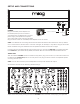
MOTHER-32 OVERVIEW The Mother-32 is a semi-modular analog synthesizer. Each function has been designed as a module, and useful parts of each module are “pre-wired” on the internal circuit board for making sound. This means that your Mother-32 will produce sound at its output without any patch cables in use. Extended synthesis capabilities are easily accessible via the 32-point, 3.5mm patchbay.
PANEL CONTROLS & FUNCTIONS VCO (VOLTAGE CONTROLLED OSCILLATOR) FREQUENCY This control is used to tune the oscillator’s pitch up or down one octave from its center position. This is useful for ensuring that Mother-32 is in tune with other instruments, or can also be used as a live performance control. NOTE: This is an analog control and is calibrated at the factory to provide slightly more than +/-1 octave from center.
VCO MODULATION VCO MOD SOURCE This switch is used to determine whether the LFO, EG or an external modulation source is being sent to the VCO MOD AMOUNT control. NOTE: If an external modulation source is patched into the VCO MOD input patch point, and EG/VCO MOD is selected as your VCO MOD SOURCE, only the external modulation signal will be applied to the VCO MOD AMOUNT control. VCO MOD AMOUNT This variable control determines how much modulation is applied to the selected VCO Mod Destination.
LFO (LOW FREQUENCY OSCILLATOR) Essentially, an LFO allows you to move a parameter’s value up and down automatically. LFOs generate repeating waveforms in the sub-audio range, which are useful for creating repeating effects like pitch vibrato, filter sweeps or pulse width modulation. The Mother-32’s LFO is also capable of audio-rate modulation, which can be used to add harmonic complexity to any selected destination.
VCF (VOLTAGE CONTROLLED FILTER) The Filter is selectable between a classic Moog 24dB/Octave Low Pass Filter with Resonance and a classic Moog 24dB/Octave High Pass Filter. CUTOFF Use this control to change the Filter’s Cutoff frequency from 20Hz to 20kHz. In LOW PASS mode, only frequencies below the selected Cutoff frequency are allowed to pass through. Turning the CUTOFF control to the right will open the Filter, creating a brighter sound.
VCF MODULATION VCF MOD SOURCE This switch is used to determine whether the LFO or EG is being sent to the VCF MOD AMOUNT control. VCF MOD AMOUNT This variable control determines how much the modulation source changes the Filter Cutoff frequency. VCF MOD POLARITY This switch is used to determine whether the VCF modulation has a positive or negative effect on the Filter Cutoff frequency.
EG (ENVELOPE GENERATOR) (continued) SUSTAIN When ON, the Envelope signal will hold at its maximum level for the duration a note is held, similar to an organ. When OFF, the Attack stage immediately moves to the Decay stage when complete, or when a note is released depending on which occurs first. NOTE: When the Sustain switch is set to ON, overlapping notes from the Keyboard or MIDI notes do not retrigger the EG, allowing legato phrasing.
KEYBOARD OVERVIEW KEYBOARD The Mother-32 has a single-octave 13-note keyboard with LEFT/RIGHT arrow buttons used for selecting the octave of the keyboard. There are 8 available octave settings, indicated by 8 OCTAVE / LOCATION LEDs lit red. The keyboard is also used to access a number sequencer functions. NOTE: There are two performance modes for the keyboard and octave buttons: Keyboard mode and Step mode. They determine how these buttons interact with the Sequencer.
SEQUENCER PANEL CONTROLS (continued) PATTERN (BANK) This button is used to view the currently active pattern location, or select a new pattern. While holding the (SHIFT) button, it is used to view the current Bank containing 8 patterns, or select a new Bank. RUN/STOP (REC) This button is used to start the Sequencer, and to stop it. While holding the (SHIFT) button, this is used in Keyboard mode to initiate the Record function. NOTE: Holding (SHIFT)+(REC) for over a second will start the saving process.
MIDI INPUT MIDI IN The Mother-32 has a 5-pin DIN MIDI input that allows for external MIDI control, MIDI clock sync and MIDI to CV conversion. When MIDI information is being received, the MIDI IN LED will flash red. Details of the MIDI implementation are contained in the “MIDI Functions and Implementation” section of this manual.
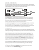
UNDERSTANDING & USING THE MOTHER-32 SEQUENCER BASIC CONCEPTS A sequencer is used to play notes or rests on a synthesizer from a pattern in memory, typically at a steady tempo. Each note or rest in the pattern is called a “step”. On each step, the sequencer outputs a CV signal to control the VCO, a Gate signal to trigger the EG, and if desired, an Accent signal which modulates the VCF and VCA for emphasizing notes.
TUTORIAL - CREATING A PATTERN IN KEYBOARD MODE This is a tutorial that will walk you through the sequencing capabilities of your Mother-32 in KB mode. Keyboard mode is the best place to start when learning to use the Sequencer. Before starting, disconnect any patch cables and set all controls to the default positions found on Page 7. INITIALIZE THE CURRENT PATTERN + Press (SHIFT)+RESET+PATTERN simultaneously to initialize the current pattern.
KB MODE TUTORIAL - CREATING A PATTERN (continued) SET THE GATE LENGTH Set the GATE LENGTH control to minimum. The Octave/Location LEDs temporarily light red to indicate the current Gate Length. = Gate Length is set per-step and determines the duration that a note is held relative to the length of its step (from 1/8 - 8/8). Short durations (counterclockwise) can be used to create staccato notes, while the longest duration (clockwise) acts as a “Tie”.
KB MODE TUTORIAL - CREATING A PATTERN (continued) TURNING GLIDE ON/OFF To turn Glide ON for a step, simply turn the GLIDE control to the right. Octave/Location LED 5 is lit green indicating Glide is turned ON for the current step. To turn Glide OFF for a step, simply turn the GLIDE control all the way down. = Indicates Glide Is On (Green LED) NOTE: Glide rate is not set per-step and is always determined by the front panel GLIDE control.
KB MODE TUTORIAL - CREATING A PATTERN (continued) ADD A RATCHET TO STEP 6 = + Yellow LEDS Green LED Hold (SHIFT) while turning the GLIDE control. Octave/Location LEDs 1-4 will temporarily light yellow, indicating the number of Ratchets (repeats) in the current step. Select a value of 2, which will produce 2 notes during the step (up to 4 can be selected). Octave/Location LED 6 is lit green to indicate a Ratchet value greater than 1.
PLAY A PATTERN RUN THE PATTERN Adjust the TEMPO control to the speed you want, and press RUN/STOP. The Sequencer will advance through each step in the pattern. When it reaches the end, it loops around to Step 1. The current step being played is indicated by the corresponding Step LED being lit. PAUSE A PATTERN To pause a pattern at the last step played, press RUN/STOP. Pressing RUN/STOP again will resume playback from the next step in the pattern.
SEQUENCER PERFORMANCE FUNCTIONS LIVE ACCENT + Press (SHIFT)+ACCENT during playback to temporarily add an Accent to each step in a pattern. Live Accent overrides stored Accent data and is only active when both buttons are held. Live Accent data is not stored in memory. + Press (SHIFT)+REST during playback to temporarily Mute the output of the sequencer as it continues to advance. Live Mute is only active as long as these buttons are held and is not stored in memory.
KB MODE PATTERN EDITING To make changes to an existing pattern using the Record function with step write behavior, press (SHIFT)+(REC) when the pattern is paused. + Steps with data entered will be lit. Octave/Location LED 1 will be lit green to indicate Page 1 of the pattern. Step LED 1 will blink at the current tempo, indicating that it can be edited.
SAVING A PATTERN Any changes to the current pattern are discarded when changing to a new pattern unless they are saved. Blinking Green LED Indicates Save Destination + To Save a pattern, hold (SHIFT)+RUN/STOP for one second. An Octave/Location LED will rapidly blink green indicating the current destination for saving. Select Pattern Location To Save in the current location, simply press (SHIFT)+RUN/STOP.
INITIALIZING A PATTERN + Press (SHIFT)+RESET+PATTERN to initialize the current pattern. This does not affect any data stored in memory, but it will discard any unsaved changes to a pattern. + CURRENT BANK AND PATTERN LOCATION + = Indicates Current Bank (Green LED) = To check the bank of a pattern currently in use, press (SHIFT)+(BANK). One of eight green Octave/Location LEDs will be lit showing the current bank. To check the location of a pattern currently in use, press PATTERN.
STEP MODE TUTORIAL - CREATING A PATTERN (continued) SETTING PATTERN LENGTH Set End Step Select End Step You can create a pattern with up to 32 steps, however, in this case we are going to set the pattern length to be eight steps. Press SET END and then press Step 8. All eight Step LEDs are now lit solid and blink only when the pattern advances through them. All notes are currently the same, so you need to edit each step to make the pattern more interesting.
STEP MODE TUTORIAL - CREATING A PATTERN (continued) EDITING NOTES Play A New Note For The Selected Step Select Octave Select octave 4 with the LEFT/RIGHT arrows and play the “G” key (located above Step LED 5). As the pattern continues to play back, you will hear the new note on Step 2. Now rotate the GATE LENGTH control fully clockwise so that the maximum Gate Length (Tie) is selected. Now the note will be held during the transition to the next step. EDITING STEP 3 Press (SHIFT)+Step 3.
STEP MODE TUTORIAL - CREATING A PATTERN (continued) ADDING ACCENTS TO STEP 1, STEP 4 AND STEP 7 Select Step To Add Accent To + + Press (SHIFT)+Step 1. Step LED 1 will blink to indicate it is selected for editing. Press ACCENT. Octave/Location LED 7 will be lit yellow. Press (SHIFT)+Step 4. Step LED 4 will blink to indicate it is selected for editing. Press ACCENT. Octave/Location LED 7 will be lit yellow. Press (SHIFT)+Step 7. Step LED 7 will blink to indicate it is selected for editing. Press ACCENT.
PLAYING AND EDITING A PATTERN IN STEP MODE Pattern Page Selectors Rotate Controls Set End Step Turning ON or OFF Individual Steps Or Selecting Steps To Edit The Mother-32 Step mode repurposes the 13-note Keyboard and LEFT/RIGHT arrows to be performance controls for modifying patterns during playback. The eight buttons directly above the Step LEDs are the Step buttons. They are used for turning On or Off individual steps or for selecting steps for editing.
SEQUENCER PANEL FUNCTION QUICK REFERENCE SEQUENCER MEMORY AND LOADING A PATTERN SELECT BANK + + Or While holding (SHIFT)+PATTERN, use Step buttons 1-8, or the LEFT/RIGHT arrows to select a new bank. SELECT PATTERN + Or While holding PATTERN, use Step buttons 1-8, or the LEFT/RIGHT arrows to select a new pattern. NOTE: Unsaved changes to a pattern will be lost when a pattern location is changed, initialized, or restored during normal operation. SAVING A PATTERN Hold (SHIFT)+RUN/STOP for 1 second.
SEQUENCER PANEL FUNCTION QUICK REFERENCE (continued) MODE SELECTION KB (KEYBOARD) Press (SHIFT)+(KB). + STEP Press (SHIFT)+(STEP). + SEQUENCER CONTROLS SET INTERNAL CLOCK TEMPO Rotate the TEMPO control. START/PAUSE PATTERN PLAYBACK Press RUN/STOP. RETURN TO STEP 1 Press RESET. REPEAT CURRENT STEP DURING PLAYBACK Press HOLD while the sequencer is running. Normal playback resumes on release. MOMENTARY ACCENT DURING PLAYBACK Hold (SHIFT)+ACCENT. Normal playback resumes on release.
SEQUENCER PANEL FUNCTION QUICK REFERENCE (continued) SEQUENCER CONTROLS (continued) MOMENTARY MUTE DURING PLAYBACK Hold (SHIFT)+REST. Normal playback resumes on release. + MOMENTARY RATCHETS DURING PLAYBACK Hold (SHIFT) and rotate the GLIDE Control. Normal playback resumes on release. + MODIFY SWING Press (SHIFT) and rotate the TEMPO Control.
SEQUENCER PANEL FUNCTION QUICK REFERENCE (continued) KB MODE PANEL FUNCTIONS (continued) GATE LENGTH | STEP MODE Rotate the GATE LENGTH control to modify the Gate Length of a currently selected step. Maximum Gate Length ties the selected step to the next step. ACCENT | KB MODE Press ACCENT to add an Accent to the current step. Octave/Location LED 7 is green when Accent is On. REST | KB MODE Press REST to add a Rest to the current step and advance to edit the next step.
SEQUENCER PANEL FUNCTION QUICK REFERENCE (continued) KB MODE PANEL FUNCTIONS (continued) Select Page Of End Step SET END STEP | KB MODE Set End Step Press (SHIFT)+SET END. If the desired end step is on a different page, press (SHIFT)+Page button 1-8, 9-16, 17-24 or 25-32. To specify the last step in the current pattern, press (SHIFT)+Step button 1-8.
SEQUENCER PANEL FUNCTION QUICK REFERENCE (continued) STEP MODE PANEL FUNCTIONS (continued) STEP EDIT | STEP MODE + Press (SHIFT)+Step button 1-8 to select it for editing whether the sequencer is Specify Step For Editing running or stopped. The currently selected Step LED will blink and all other Step LEDs are turned off to indicate the step being edited. The Tempo LED also blinks yellow alternating with the clock to indicate a step is being edited.
CONTROL VOLTAGE OVERVIEW Control voltages are signals used to modify circuits in an analog synthesizer. They can affect the pitch of a VCO, the timbre produced at the output of a VCF, or the loudness at the output of a VCA. A simple example is the VCO FREQUENCY control. It generates a voltage based on its rotation that is connected to the control input of the VCO. When you turn it counterclockwise, the voltage and VCO pitch are reduced. When you turn it clockwise, the voltage and VCO pitch are increased.
PATCHBAY INPUTS AND OUTPUTS EXTERNAL AUDIO INPUT EXTERNAL AUDIO INPUT This is a unity gain input that allows other sound sources to be processed by Mother-32’s onboard Filter. Because this is a unity gain input designed to Eurorack level standards, an external audio source applied to this input should be 10V peak to peak. Signals lower than this (an MP3 player for instance) will need to be amplified prior to being input to the EXT. AUDIO jack for proper volume performance levels.
PATCHBAY INPUTS AND OUTPUTS (continued) NOISE NOISE OUTPUT This is the output for the Mother-32’s White Noise generator. Noise is useful for creating percussion and wind sounds, as well as for random noise modulations (+/-5V, typical). NOTE: Noise is also normalled to the clockwise position of the main MIX control. VOLTAGE CONTROLLED FILTER VCF CUTOFF INPUT This input is summed with the Filter CUTOFF control and the VCF Modulation signal.
PATCHBAY INPUTS AND OUTPUTS (continued) VOLTAGE CONTROLLED OSCILLATOR (continued) VCO LIN FM INPUT This is a Linear Frequency Modulation input, which is useful for modulating the VCO with audio rate waveforms to achieve very harmonically rich sounds. (Accepts a -5 to +5V signal). VCO MOD INPUT This input is routed to the UP position of the VCO MOD SOURCE selector switch (EG/VCO MOD).
PATCHBAY INPUTS AND OUTPUTS (continued) LOW FREQUENCY OSCILLATOR (continued) LFO SQ OUTPUT This output is the LFO Square waveform (+/-5V). LFO TRI OUTPUT This output is the LFO Triangle waveform (+/-5V). VC MIX - VOLTAGE CONTROLLED, DC COUPLED MIXER MIX 1 INPUT This input is normalized to 0V and routed to the counterclockwise position of the VC MIX control. This is a DC coupled input and accepts a -5 to +5V CV.
PATCHBAY INPUTS AND OUTPUTS (continued) VC MIX - VOLTAGE CONTROLLED, DC COUPLED MIXER (continued) VC MIX OUTPUT This is the output of the VC Mixer which is a blend of the MIX 1 and MIX 2 input signals set by the VC MIX panel control and VC MIX CTRL CV input. (+/-5V). VC MIX ALTERNATE USES: FIXED VOLTAGE SOURCE With nothing plugged into the MIX 1 or MIX 2 inputs, the VC MIX control allows the VC MIX output to transmit a variable fixed voltage from 0 to +5V.
PATCHBAY INPUTS AND OUTPUTS (continued) ASSIGNABLE OUTPUT ASSIGN OUTPUT This is the output for the assignable jack. Its source is programmed in Setup mode. To learn more about Setup mode, go to Page 49. The following output sources are available: 1: ACCENT (Default) This outputs a 0 to +5V filtered pulse signal from Accented pattern steps only. 2: CLOCK This outputs a 0 to +5V Clock signal at the internal clock tempo, one pulse per step.
PATCHBAY INPUTS AND OUTPUTS (continued) ENVELOPE GENERATOR GATE INPUT This input accepts a 0 to +5V gate signal to trigger the EG. Tolerant of 10V gates. EG OUTPUT This is the output of Mother-32’s onboard Envelope Generator. Its behavior is directly related to the panel Envelope settings for Attack, Decay and Sustain. (0 to +7.5V) KEYBOARD The Mother-32 has a 13-note keyboard that is also used to program the sequencer.
PATCHBAY INPUTS AND OUTPUTS (continued) CLOCK/TEMPO OVERVIEW The steps of an analog sequencer are advanced by a signal called a “clock”, which is an equally spaced series of pulses. During playback, each clock pulse advances the pattern by one step. Your Mother-32 has an internal clock that is used to advance through the steps of an active pattern. The tempo of this clock signal is indicated by the Tempo LED located above the (SHIFT) button.
PATCHBAY INPUTS AND OUTPUTS (continued) CLOCK/TEMPO (continued) RUN/STOP When a +5V signal is applied to this input, the sequencer will play from its current pattern location for the duration that the voltage is applied. When a 0V signal is applied to this input, the sequencer will stop at its current pattern location. The sequencer responds to the last action of either the RUN/STOP button or this input.
MIDI FUNCTIONS AND IMPLEMENTATION MIDI CHANNEL The Default MIDI Channel is 1. The MIDI Channel can be programmed in Setup Mode. See Page 49 for details on selecting a MIDI Channel. MIDI NOTE ON The Mother-32 responds to MIDI Note On messages on the current MIDI Channel (default Channel 1). MIDI Note values received are converted into a 1V/Octave Keyboard CV, and then routed to the VCO and KB CV output jack. MIDI Note 0 corresponds to -5V, and MIDI Note 120 corresponds to +5V.
MIDI FUNCTIONS AND IMPLEMENTATION (continued) MIDI SYSTEM REAL TIME MESSAGES MIDI CLOCK MESSAGES: When the Mother-32 detects a MIDI Clock signal, the Tempo LED blinks green at the detected tempo and the panel TEMPO control becomes a clock divider. After MIDI clock messages cease to be received, the internal clock can be restarted by pressing the RUN/STOP button. MIDI START: A MIDI Start message runs the pattern from Step 1. MIDI STOP: A MIDI Stop message stops the pattern on the last active step.
SETUP MODE (continued) PARAMETER SELECTION 9-16 Select Values 9-16 + To access values 9-16, press (SHIFT)+Step buttons 1-8 (9-16). The value is indicated by red Octave/Location LEDs. If a setting is on the same LED as the current page, the LED will flash alternately between the yellow page color and the green or red setting color.
VCO CALIBRATION Your Mother-32 is fully calibrated at the factory before packaging and shipping. Because it is designed to play with external analog gear, which may or may not be well-calibrated, provisions have been made for tuning the VCO without opening the unit. There are 4 small holes in the front panel to access the most important calibrations for the VCO: VCO Offset, Frequency Control Gain, External 1V/Oct Gain, and KB CV Gain.
CALIBRATION (continued) 12. Verify that the pitch is 2 octaves higher (C6 - 1046.5Hz). Note that a pitch within 2 to 3 cents of the target frequency should be fine. Adjust the KB CV Gain trimpot ONLY if necessary. 13. Repeat steps 9 to 12 to recheck the tuning and make adjustments ONLY if necessary. 14. Now set the Keyboard Octave to “5” and press the low C on the keyboard (KB CV outputs 0V). 15. Connect a properly calibrated, 1V/Octave source outputting 0V (C4) to the VCO 1V/OCT input jack. 16.
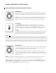
PRESETS NOTE: Additional presets and blank patch sheets can be downloaded at www.moogmusic.com OCTAVE BOUNCE BACK (Adjust VC MIX to control tuning) 7.b NOISE TRANSIENT 7.b METAL SNARE 7.
SEQUENCER BASS 7.b RESONANT HIGH PASS FILTER 7.
‘80S TOMS 7.b SHORT BRASS 7.
PRESET NAME: 7.b NOTES: PRESET NAME: 7.
PRESET NAME: 7.b NOTES: PRESET NAME: 7.
SPECIFICATIONS SOUND ENGINE: 100% Analog KEYS: 13 Momentary Pads POLYPHONY: Monophonic DIMENSIONS: 12.57“W x 4.21“H (with knobs) x 5.24“D WEIGHT: 3.5 lbs. POWER CONSUMPTION: 2.8W INCLUDED POWER SUPPLY: 100-250VAC, 50-60Hz, +12VDC 1A PATCHBAY: 32 x 3.5mm jacks REAR PANEL AUDIO OUT: 1/4” Headphone / Audio EURORACK SPECS CURRENT DRAW: 230mA (maximum) from +12VDC (10-pin header) MOUNTING DIMS: 60HP (.
SERVICE AND SUPPORT INFORMATION MOOG’S STANDARD WARRANTY Moog warrants its products to be free of defects in materials or workmanship and conforming to specifications at the time of shipment. The Warranty Period is one year from the date of purchase. If, in Moog’s determination, it has been more than five years since the product shipped from our factory, it will be at Moog’s discretion whether or not to honor the warranty without regard to the date of the purchase.
Mother-32 Is Handcrafted With Care By Employee-Owners In Asheville, NC 60