
User Manual


27
PATCHBAY OVERVIEW (Continued)
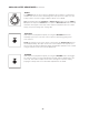
VCO EG (VCO EG CONTROL VOLTAGE OUTPUT)
This output provides a copy of the control voltage used to modulate the
VCOs internally.
OUTPUT
0V to +8V Control Voltage
NOTE: The VCO EG output voltage is informed by the Sequencer VELOCITY 1-8
knobs and the VCO DECAY knob.
VCF MOD (VCF MODULATION CONTROL VOLTAGE INPUT)
Plugging a control voltage into this jack replaces the Noise Generator as a hard-
wired modulation source for the VCF. The maximum amount of modulation
applied to the Filter will still be controlled by the NOISE / VCF MOD knob.
INPUT
-5V to +5V Control Voltage
NOTE: The VCF MOD input is the only means of directly applying a control
voltage to the Filter’s Cutoff Frequency. For complete CV control over the Filter, ensure that the
NOISE / VCF MOD knob is set to its maximum position.
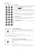
VCO 1 CV (VCO 1 CONTROL VOLTAGE INPUT)
This input provides 1V/Octave control over the Pitch of Oscillator 1. It is summed
with the VCO 1 FREQUENCY knob, the VCO 1 EG AMOUNT knob, and the
individual Sequencer PITCH 1-8 knobs (if the SEQ PITCH MOD switch is set to
VCO 1&2).
INPUT
-5V to +5V Control Voltage
NOTE: For accurate 1V/Octave control over the Pitch of Oscillator 1, set the VCO 1 FREQUENCY and VCO
1 EG AMOUNT knobs to their middle positions, and ensure that the SEQ PITCH MOD switch is set to OFF
or VCO 2.
VCO 1 (VCO 1 SIGNAL OUTPUT)
This is the direct output of Oscillator 1. It can be used as a sound source or as a
modulation source.
OUTPUT
-5V to + 5V (10V peak to peak)
NOTE: The VCO 1 output is affected by the VCO 1 FREQUENCY knob, the VCO 1
WAVE switch, the VCO 1 EG AMOUNT knob, and the individual Sequencer PITCH
1-8 knobs (if the SEQ PITCH MOD switch is set to VCO 1&2).