IMPORTANT SAFETY INSTRUCTIONS WARNING - WHEN USING ELECTRIC PRODUCTS, THESE BASIC PRECAUTIONS SHOULD ALWAYS BE FOLLOWED: 1. Read all the instructions before using the product. 2. Do not use this product near water - for example, near a bathtub, washbowl, kitchen sink, in a wet basement, or near a swimming pool or the like. 3. This product, in combination with an amplifier and headphones or speakers, may be capable of producing sound levels that could cause permanent hearing loss.
TABLE OF CONTENTS 06 UNPACKING & INSPECTION 06 SETUP & CONNECTIONS 07 07 08 DFAM OVERVIEW Signal Flow Exploring The DFAM 13 13 16 17 20 22 24 PANEL CONTROLS & FUNCTIONS Voltage Controlled Oscillators Mixer Voltage Controlled Filter Voltage Controlled Amplifier Analog 8-Step Sequencer Patchbay 30 SYNCING MULTIPLE DFAMS 31 SYNCING DFAM WITH A MOTHER-32 32 USING DFAM AS A EURORACK MODULE 33 PRESETS & PATCH SHEETS 40 SPECIFICATIONS & ACCESSORIES 41 SERVICE & SUPPORT INFORMATION
UNPACKING AND INSPECTION Be careful when unpacking your new Drummer From Another Mother so that nothing is lost or damaged. We recommend saving the carton and all packing materials in case you ever need to ship the instrument for any reason. The Moog DFAM ships with the following items: 1. 2. 3. 4. 5. 6. DFAM Semi-Modular Analog Percussion Synthesizer Power Supply Owner’s Manual Overlays Patch Cables Registration Card What you will need: 1.
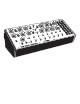
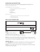
DFAM OVERVIEW Your new Drummer From Another Mother (DFAM) is a highly-interactive, Semi-Modular Analog Percussion Synthesizer and a vibrant deviation from the traditional drum machine. As an addition to the Mother-32 family of Semi-Modular Analog Synthesizers, DFAM presents a uniquely expressive hands-on approach to percussive pattern creation.
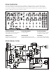
EXPLORING THE DFAM This hands-on tour of your DFAM will give you a basic foundation with which visceral rhythms can be synthesized. There are loads of tips, tricks and patching suggestions contained within this manual, but if you want to just jump to making cool sounds – go to page 33. DEFAULT SETTINGS Start by setting your DFAM to the Default settings shown above. START THE SEQUENCER Push the RUN / STOP button to start the Sequencer.
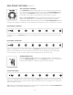
EXPLORING THE DFAM (Continued) GET THE PITCH JUMPING The VCO DECAY knob is going to add some more motion to the pitch of the note. It works in conjunction with the position of the VCO EG AMOUNT knobs. Try turning the VCO DECAY knob up slowly and listen to how it affects the sound. When you’re done experimenting, set this knob to 9 O’clock. TIP: The VCO EG AMOUNT knob plays an extremely important role in how the DFAM sounds and behaves. It is the difference between a silly sound and a slamming kick drum.
EXPLORING THE DFAM (Continued) CHANGING THE WAVEFORMS Let’s change up the sound. Set the VCO 1 WAVE switch to the SQUARE wave position and listen to how it affects the sound. ADDING AN OSCILLATOR Turn the VCO 2 LEVEL knob all the way up. CREATING HARMONY Turn the VCO 2 FREQUENCY knob to the right until it sounds in tune with VCO 1 FREQUENCY. HARD SYNC Set the HARD SYNC switch to ON. LISTENING TO HARD SYNC Now grab the VCO 2 FREQUENCY knob and turn it all the way up and down a few times.
EXPLORING THE DFAM (Continued) EXPLORING FM Gently turn the 1�2 FM AMOUNT knob to 12 O’clock and listen to how the sound is changing. You are now shaking or “modulating” the pitch of Oscillator 2 with Oscillator 1. Take a moment to experiment with how the 1�2 FM AMOUNT knob and the VCO 2 FREQUENCY knob interact with each other. Feel free to adjust these controls individually or at the same time. A lot of sounds can be created from here. NOTE: FM is much more noticeable when HARD SYNC is set to OFF.
EXPLORING THE DFAM (Continued) NOISE AS A MODULATION SOURCE Now slowly turn the NOISE / VCF MOD knob all the way up. Notice the difference when Noise is used as a Modulation Source for the Filter. Instead of creating depth, it makes the sound seem distorted or lo-fi. SET THE NOISE MODULATION Set the NOISE / VCF MOD knob to 9 O’clock. SHORTENING VCA DECAY Turn the VCA DECAY knob to 10 O’clock and listen to how the sound tightens up.
PANEL CONTROLS & FUNCTIONS VOLTAGE CONTROLLED OSCILLATORS (VCO) In an analog synthesizer, oscillators are the primary source of sound. Your Drummer From Another Mother contains two Voltage Controlled Oscillators, also referred to as VCOs. VCO 1 FREQUENCY / VCO 2 FREQUENCY The VCO FREQUENCY knobs specify the starting Pitch of each Oscillator over a ten-octave range.
OSCILLATOR INTERACTION DFAM’s Oscillators can interact with each other to provide new timbres and to create new sounds. HARD SYNC and FM are both useful tools that can be utilized individually or at the same time. HARD SYNC When set to ON, HARD SYNC forces the phase of Oscillator 2 to match — or to be in sync with — the phase of Oscillator 1. This forced synchronization causes the waveform of Oscillator 2 to take on a more complex waveshape as it works to stay aligned with Oscillator 1.
OSCILLATOR MODULATION Changes in Oscillator pitch can come from multiple sources, but two are immediately available without patching: the Sequencer PITCH 1-8 knobs and the VCO Envelope Generator, which is itself directly affected by the Sequencer VELOCITY 1-8 knobs. SEQ PITCH MOD This three-position switch determines which Oscillators are being controlled, or modulated, by the Sequencer PITCH 1-8 knobs. VCO 1 & 2 The Sequencer PITCH 1-8 knobs are assigned to the Frequency of Oscillator 1 and Oscillator 2.
VCO 1 EG AMOUNT / VCO 2 EG AMOUNT This pair of knobs determines how much effect the VCO Envelope Generator will have on the Pitch of Oscillator 1 and Oscillator 2, respectively. All AMOUNT knobs on DFAM are bipolar, meaning that they have both positive (+) and negative (–) modulation values available. CENTER POSITION No Envelope is applied to the Pitch of the Oscillator and its Frequency remains steady.
MIXER (Continued) NOISE / EXT LEVEL This knob is used to set the level of the White Noise Generator. Its value can also be controlled via the NOISE LEVEL CV input (VCA) on the Patchbay. An External Audio signal can be used in place of the White Noise Generator by connecting it to the EXT AUDIO input jack on the DFAM Patchbay. The level of the External Audio signal would then be attenuated using this knob. NOTE: The EXT AUDIO input jack is a 3.
VOLTAGE CONTROLLED FILTER (VCF) (Continued) CUTOFF The CUTOFF knob specifies the Frequency at which the Filter begins to attenuate (or reduce) sound in either the Low Pass or High Pass mode. NOTE: The 4-pole Ladder Filter provides 24dB of attenuation per octave beginning at the Filter’s Cutoff point. LOW PASS MODE As the Filter CUTOFF knob is turned to the right, the top end of the Filter will open, resulting in a brighter and more articulate sound, while retaining lower frequency harmonics.
VOLTAGE CONTROLLED FILTER (VCF) (Continued) VCF DECAY The VCF Envelope Generator is dedicated to modulating the Cutoff Frequency of the Filter. The Decay time of this EG is set using the VCF DECAY knob. This value may also be affected by the Sequencer VELOCITY 1-8 knobs. These Velocity levels are connected to the Velocity inputs of the Envelope Generators, providing an additional source of voltage control to both the Amplitude and Decay Time of the VCF EG.
VCF EG AMOUNT (Continued) (-) AMOUNT As the VCF EG AMOUNT knob is rotated to the left of center, negative Envelope Modulation is applied to the Filter’s Cutoff Frequency. This causes the Filter Cutoff Frequency to be decreased, regardless of the VCF switch setting. Negative VCF EG AMOUNT settings result in dips or large drops in Filter Frequency as each note is played, creating sounds that may be perceived as blooming, boingy, or somewhat videogame-esque in character.
VCA DECAY The third and final Envelope Generator in your DFAM is dedicated to modulating the Output volume of the VCA. The Decay time of this EG is set using the VCA DECAY knob. This value may also be affected by the Sequencer VELOCITY 1-8 knobs. These Velocity levels are connected to the Velocity inputs of the Envelope Generators, providing an additional source of voltage control to the Amplitude and Decay time of the VCA EG.
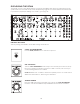
ANALOG 8-STEP SEQUENCER Your Drummer From Another Mother includes an all-analog 8-Step Sequencer with two rows of knobs. One is for PITCH; the other is for VELOCITY. Together, they provide the tools for crafting dynamic and expressive rhythmic percussion patterns. STEP CONTROLS Each Sequencer step (1—8) features a PITCH knob, a VELOCITY knob, and an LED that indicates the currently active step.
ANALOG 8-STEP SEQUENCER (Continued) TEMPO The TEMPO knob sets the Sequencer playback speed, which is continuously variable from .7Hz to 700Hz. Assuming each step represents a 16th note, the Tempo can be set from roughly 10 BPM to about 10,000 BPM. TIP: Try patching from the PITCH CV or VELOCITY CV output, into the TEMPO CV input. The Sequencer PITCH 1-8 or Sequencer VELOCITY 1-8 knobs will now determine the length of each step in the sequence.
PATCHBAY PATCHBAY The DFAM Patchbay is equipped with 24 x 3.5mm patch points, which allow for extended synthesis capabilities and modular interconnectivity. There are 15 inputs LABELED in standard text, and 9 outputs identified by REVERSE lettering. The Patchbay is designed to work with 3.5mm patch cables only. A pack of five is included with your DFAM. If you should need more, 6" and 12" packs of Moog cables are available for purchase at authorized Moog dealers.
PATCHBAY (Continued) VCA (AUDIO OUTPUT) This is the main audio output of the internal VCA set by the VOLUME knob. OUTPUT -5V to +5V Audio Signal at typical Eurorack levels VELOCITY (VELOCITY CONTROL VOLTAGE INPUT) This input controls the maximum amplitude of DFAM’s Envelope Generators, and is one of the keys to DFAM’s highly dynamic and expressive sound. INPUT 0V to +5V Control Voltage NOTE: The VELOCITY input is normalled (or hard-wired) to the Sequencer VELOCITY 1-8 knobs.
PATCHBAY OVERVIEW (Continued) VCF DECAY (VCF DECAY CONTROL VOLTAGE INPUT) This input determines the Decay Time of the VCF EG and is useful for creating large variations in timbre for more complex sounds. INPUT -5V to +5V Control Voltage NOTE: The VCF DECAY input is summed with the manual VCF DECAY knob. Setting the VCF DECAY knob to its middle position will offer the widest range of values from an external CV signal.
PATCHBAY OVERVIEW (Continued) VCO EG (VCO EG CONTROL VOLTAGE OUTPUT) This output provides a copy of the control voltage used to modulate the VCOs internally. OUTPUT 0V to +8V Control Voltage NOTE: The VCO EG output voltage is informed by the Sequencer VELOCITY 1-8 knobs and the VCO DECAY knob. VCF MOD (VCF MODULATION CONTROL VOLTAGE INPUT) Plugging a control voltage into this jack replaces the Noise Generator as a hardwired modulation source for the VCF.
PATCHBAY OVERVIEW (Continued) 1�2 FM AMT (VCO 1 TO VCO 2 FREQUENCY MODULATION AMOUNT INPUT) This input modulates the value of the 1�2 FM AMOUNT knob to determine the amount of modulation (Linear FM ) applied to Oscillator 2 by Oscillator 1. INPUT 0V to +8V Control Voltage NOTE: A voltage applied to the 1�2 FM AMT input is summed with the position of the manual 1�2 FM AMT knob. VCO 2 CV (VCO 2 CONTROL VOLTAGE INPUT) This input provides 1V/Octave control over the Pitch of Oscillator 2.
PATCHBAY OVERVIEW (Continued) RUN / STOP (GATE INPUT) This input allows an external voltage to start and stop the DFAM Sequencer. When a +5V signal is applied to this input, the Sequencer will play from its current pattern location for the duration that the voltage is applied. When a 0V signal is applied to this input, the Sequencer will stop at its current pattern location.
SYNCING MULTIPLE DFAMS To Sync multiple DFAM units together, simply patch from the TRIGGER output on the Patchbay of the Primary unit, into the ADV / CLOCK input on the Secondary unit. PRIMARY UNIT SECONDARY UNIT Press RUN / STOP on the Secondary unit first. This will ensure that it is ready to play when it begins receiving a Clock signal from the Primary unit. SECONDARY UNIT Press RUN / STOP on the Primary unit. Both units should now be playing in sync.
SYNCING DFAM WITH A MOTHER-32 To Sync your DFAM to a Mother-32, simply patch from the ASSIGN output jack on the Mother-32 Patchbay, into the ADV / CLOCK input on the DFAM. IMPORTANT NOTE: You will need to ensure that the Mother32’s Assignable output is set to transmit clock. To learn more about Mother-32’s Assignable output, see pages 44, 49, and 50 in the Mother-32 User’s Manual. MOTHER-32 DFAM Press RUN / STOP on your DFAM.
USING DFAM AS A EURORACK MODULE Your Drummer From Another Mother can be removed from its case, and easily installed into a Eurorack system as a 60HP module. Before doing this, it is important to note that the DFAM draws a maximum of 230mA from a +12V supply. It does not use the -12V supply at all. Make sure there is enough headroom on the +12V supply in your system to power the DFAM.
PRESETS Please note that your DFAM is 100% analog, and as a result, each unit has subtle sonic differences due to component tolerances that make it unique. This means that two different units set the same way may sound slightly different. This is normal. MUSIC BOX NOTE: Additional presets and blank patch sheets can be downloaded at www.moogmusic.com.
FM TOYS NOTES • VCO 2 is modulating the Filter Cutoff • Try adjusting the VCO 2 FREQUENCY knob • Listen to the difference between the VCF in LP and HP mode SEQUENCED BASS NOTES • Use the VCO FREQUENCY knobs to ensure VCO 1 and VCO 2 are exactly in tune • Minor adjustments to the Sequencer PITCH 1-8 knobs will add motion to your bass line • Tweak the Filter CUTOFF knob to taste 34
KICK / SNARE / FM OSC 2 NOTES • The Sequencer PITCH 1-8 knobs determine the voicing for each step • The Sequencer PITCH 1-8 knobs also determine the Snare volume • Turn the Sequencer VELOCITY 1-8 knobs up and down to vary the Kick pattern FILTER AS AN OSCILLATOR NOTES • The Filter CUTOFF knob is being controlled by the Sequencer PITCH 1-8 knobs • Turn up the VCO 2 LEVEL control to add a watery wobble • Increasing the NOISE / EXT LEVEL will add a more ghostly tone to the sound 35
INSANE TOMS NOTES • VCO 2 is adding extra triggers • Try experimenting with the VCO 2 EG AMOUNT knob • The Sequencer PITCH 1-8 knobs determine how each hit rings out SWING TIME NOTES • The Sequencer PITCH 1-8 knobs determine the length of each Step in a Sequence • Lower Sequencer PITCH settings will result in extremely long step lengths • Higher Sequencer PITCH settings will result in extremely short step lengths 36
SEQUENCER AS AN OSCILLATOR NOTES • The VCO 1 FREQUENCY knob controls the Sequencer Rate and Pitch • The Sequencer PITCH 1-8 knobs alter and shape the waveform • Add some VCO 2 LEVEL for wild sounds TALKING DRUM NOTES • VCO 2 is modulating the Filter Cutoff position • The NOISE / VCF MOD knob determines how vocal the drum is • Turn the RESONANCE knob down to add more thump 37
PRESET NAME: NOTES PRESET NAME: NOTES 38
PRESET NAME: NOTES PRESET NAME: NOTES 39
SPECIFICATIONS ANALOG SOUND ENGINE SOURCES: VCO 1, VCO 2, White Noise Generator FILTER: Selectable High Pass/Low Pass 4-pole (-24dB/Oct) Ladder Filter MODULATION: VCO EG with Voltage Controlled Decay, VCF EG with Voltage Controlled Decay Time, VCA EG with with Voltage Controlled Decay Time and selectable Attack Time ANALOG SEQUENCER CONTROL: 8 Steps with dedicated PITCH and VELOCITY knobs per step TEMPO: 10 BPM to 10,000 BPM OTHER: Manual Trigger and Advance buttons PATCHBAY JACKS: 24x 3.
SERVICE AND SUPPORT INFORMATION MOOG’S STANDARD WARRANTY Moog warrants its products to be free of defects in materials or workmanship and conforming to specifications at the time of shipment. The Warranty Period is one year from the date of purchase. If, in Moog’s determination, it has been more than five years since the product shipped from our factory, it will be at Moog’s discretion whether or not to honor the warranty without regard to the date of the purchase.
Moog Music Is An Employee-Owned Company Located In Asheville, NC 44