
User Guide


26
UTILITIES (Continued)
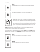
INPUT
An audio signal connected here will be processed by the High Pass Filter.
OUTPUT
The audio signal available here is the output of the High Pass Filter.
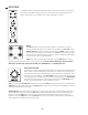
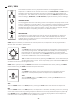
ATTENUATOR (BIPOLAR)
An Attenuator is used to reduce the strength of a control signal to provide
more accuracy when modulating a specic parameter value. This Attenuator
can also deliver both normal and inverted values. In the center position,
the ATTENUATOR knob provides its full effect, and any input signal is fully
attenuated. Raising the value clockwise from center will provide less and
less attenuation, until the full scale of the input signal is restored and passed
through unaffected. Lowering the value counterclockwise from center will
provide less and less attenuation of the inverted signal, until the full value of
the inverted signal is restored at the full counterclockwise position.
NOTE: Negative (or inverse) modulation simply ips the control signal, so that any control signal
previously raising the value of a parameter would now be lowering it.
TIP: The input to the attenuator is normalled to a positive voltage. With nothing patched to its input, the
output is a DC source of -/+ 8V. Try patching from the Attenuator OUTPUT jack to the RATE IN jack of the
Modulation section. You can now use the ATTENUATOR knob to add to, or subtract from, the minimum or
maximum panel values of the Modulation RATE knob.
INPUT
Any signal connected here will be processed by the Attenuator.
OUTPUT
The signal available here is the output of the Attenuator.
0
+
-