
User Guide


24
MODULATION (Continued)
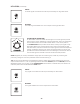
PULSE WIDTH AMT (AMOUNT)
The PULSE WIDTH AMT knob determines the maximum depth of modulation
that will be applied to the Pulse Width of the Square and Narrow Pulse waves
of Oscillators 1 and 2 when the MOD wheel is at its maximum position.
NOTE: Pulse Width Modulation (PWM) can only be applied to an oscillator
when a square or narrow pulse wave is selected as the current waveform.
Pulse Width Modulation continuously varies the duty cycle, or pulse width,
of these waves, causing the harmonic content to continuously vary as well.
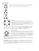
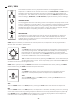
RATE IN
A control signal received here is added to the value of the RATE knob to
determine the frequency of the LFO.
TECH TIP: The RATE IN patch point is based on the 1 Volt-per-Octave standard,
allowing the LFO to be “played” like an oscillator.
SYNC IN
A gate or trigger pulse received here will reset the LFO wave to its starting point.
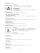
WAVE OUT
The control signal available at this output is determined by the WAVEFORM
and RATE knob settings.
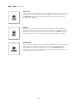
S/H OUT
Sample/Hold (S/H) is a stepped modulation effect, often used to “pulse”
the Cutoff frequency of a Low Pass lter with near random values. At the
beginning of every modulation wave cycle, the Noise generator is sampled to
acquire a control value that can be used to modulate another parameter. That
stream of Sample/Hold values is available via this output.
TIP: A control or gate signal received at the SYNC IN jack will reset the
Modulation generator to the beginning of its wave cycle, meaning the Sample
& Hold feature can be stepped by an external trigger or gate. Try patching from the GATE OUT in the
ARP / SEQ section to the SYNC IN, and set the RATE control to its minimum value. This will allow you
to use the keyboard to step through Sample & Hold values with each key press.
NOTE: There is no internal routing to use the Sample/Hold generator, so it must be patched from this
jack to a specic destination in order for it to modulate another parameter.