
User Guide


17
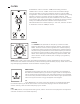
KBD TRACKING (Continued)
1:1
In the 1:1 position, the value of the note played on the keyboard will affect the Cutoff frequency at full value. This
means that playing a note two octaves above another will raise the Cutoff frequency by a full two octaves.
TECH NOTE: The Keyboard Tracking value in the 1:1 selection is 1 Volt-per-Octave.
TIP: Turn the OSCILLATOR 1 and 2 knobs in the mixer all the way down, and turn the NOISE knob half
way up. Now, set the RESONANCE knob to its middle position and set the KBD TRACK switch to 1:1.
This will allow the Filter to be played from the keyboard while also creating an eerie sound.
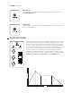
ENVELOPE AMT
The ENVELOPE AMT knob determines how much of the control signal
created by the Envelope will be applied to the Filter’s Cutoff frequency over
time. This knob is bipolar, so turning the ENVELOPE AMT knob clockwise
from center will raise the Filter’s Cutoff frequency from the CUTOFF knob’s
current setting. Turning it counterclockwise from center will lower the Filter’s
Cutoff frequency from the CUTOFF knob’s current setting.
NOTE: Negative, or inverse, modulation simply ips the shape of the
Envelope generator. Instead of the Attack parameter raising the Cutoff
frequency over time, the Attack parameter will lower the Cutoff frequency by the same amount, in the
same period of time.
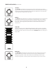
RESONANCE
Resonance takes a portion of the Filter’s output and sends it back to the input
of the Filter, creating emphasis at the Filter’s Cutoff frequency. This is useful for
adding focus, articulation, or “frickin’ laser beams” to a sound.
NOTE: Adding Resonance may reduce the overall volume or bottom-end of a
sound. This is normal.
TIP: Turn the RESONANCE knob all the way up and lower the CUTOFF knob to
about 10 O’clock to cause the Filter to self-oscillate. Then set the KBD TRACK switch to 1:1 to play the
Filter from the keyboard as a Sine wave oscillator.
INPUT
An audio signal from an internal or external module can be introduced to the
Filter using this input. Any sound source applied to this input will disconnect
the normalled Mixer Output signal from the input of the Filter.
NOTE: Do not use this input to introduce an instrument or line-level signal. The
high-impedance 1/4” INSTRUMENT IN jack on the rear panel is available for
these purposes.
OUTPUT
The audio signal exiting the Filter is available at this output.
TIP: Patching from the Output of the Filter to the Input of the High Pass Filter,
and then from the Output of the High Pass Filter to the VCA IN in the Output
section allows you to vary the low-end “weight” of a sound without affecting the
relationship between the Mixer and the Low Pass Filter.
+
-