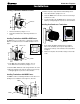
W3400 Gas Fireplace Installation Operation & Maintenance MW34-DV Gas Fireplace Warning: Improper installation, adjustment, alteration, service or maintenance can cause injury or property damage. Refer to this manual. For assistance or additional information consult a qualified installer, service agency or the gas supplier. For Your Safety: Do not store or use gasoline or other flammable vapors and liquids in the vicinity of this or any other appliance.
W3400 Gas Fireplace Table Of Contents Introduction About the Wildfire 34: Introduction ............................................................................. 2 Installation Installing the Fireplace Shell ......................................... 3 Installing the Gasline ..................................................... 4 The Remote Switch ....................................................... 4 Direct Vent Installation ..................................................
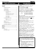
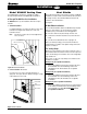
W3400 Gas Fireplace Installation Installing The Fireplace Shell The fireplace may be installed in any location that is free of air conditioning ducts, electrical wiring and plumbing. Safety, as well as efficiency of operation, must be considered when selecting the fireplace location. Try to select a location that does not interfere with room traffic, has adequate ventilation, and offers an accessible pathway for Direct Vent installation. Refer to page 4 - Vent Installation for more information.
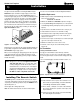
W3400 Gas Fireplace Installation Installing The Gas Line The gas line must be installed before finishing the W3400 Fireplace. Natural Gas requires a minimum inlet gas supply pressure of 5.5" W.C. & a manifold pressure of 3.5" W.C. Propane Gas requires a minimum inlet gas supply pressure of 11" W.C. & a manifold pressure of 10" W.C. Provision must also be made for a 1/8" N.P.T. plugged tapping and be accessible for test gauge connection immediately upstream of the gas supply controls to the appliance.
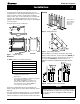
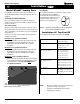
W3400 Gas Fireplace Installation Installing Terminations with Built-In Frames termination may not be easily installed from the building's exterior. 11 1. Frame the termination opening to 12" x 12". 2. Fasten the MOSR frame to the interior side of the studs using a minimum of 4 screws. 3. Insert the termination into the MOSR frame as shown here, and attach by screwing through the four pilot holes in the termination. MTO-3F 11 Installing Heat Guards over Terminations 1.
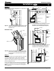
W3400 Gas Fireplace Installation Model W3400T Venting Runs For the W3400T Top Vent there are two types of installations: A) Through-The-Wall Installations and B) Vertical (Through-The-Roof) Installations. A) Through-The-Wall Installations Before you install any venting, you must determine whether the venting run will be acceptable. Unacceptable venting can affect the fireplace's combustion.
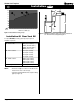
W3400 Gas Fireplace Installation W3400T Example 1: 150" max. 30" max. For our shortest venting configuration use components A and F (see Figure 9a). Heat Shield Termination Solid Sections PTKO Termination Exterior Wall PEL-90 Elbow Flex Section Hearth Figure 9a. Typical Top Vent installation. If the 90° elbow is installed directly on the fireplace, the height to the center of the termination is 44". Horizontal Venting Figure 10.
W3400 Gas Fireplace Installation Top Vent B. Vertical (Through-The-Roof) Installations Vertical Terminations must be installed: • minimum 2' (two feet) above the highest point where vent passes through the roof. • minimum 6' (six feet) from a mechanical air inlet • minimum 3' (three feet) from a parapet wall. Maximum vent height is 20 feet above fireplace. Note: Flame characteristics will change if the maximum vent height is used.
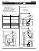
W3400 Gas Fireplace Installation Model W3400R Venting Runs For the W3400R, there are two types of installations: A) Basic Through-The-Wall Installations and B) Multi-Elbow Installations. A. Through-The-Wall Rear Vent Installations Rear Vent Heat Shields Due to high flue temperatures, heat shields are required on all W3400 installations (except those with vertical terminations) at the point where the venting connects to the termination. With the heat shield, vent clearances can be maintained at 1".
W3400 Gas Fireplace Installation Rear Vent L 108 96 84 72 60 48 H 36 24 8" 12 0 0 Hearth 12 24 36 48 60 72 84 96 108 120 132 144 156 168 180 Horizontal Run (in.) Figure 17.
W3400 Gas Fireplace Installation Finishing Around the Fireplace Combustible mantels and mouldings may be safely installed over the top and on the front of the fireplace provided that they do not project beyond shaded area shown in Figure 19. Side wall clearances are 3". Combustible surrounds may be installed with 3" clearance to the side of the fireplace as shown in Figure 20.
W3400 Gas Fireplace Installation Wiring Gas Control and Pilot Wiring 115/1/60 Supply G L1 L2 W3410 (1 or 3 fan motor) Honeywell (Q3450) Pilot Assembly Pilot Electrical Harness Connector Honeywell Gas Control (SV9501M) Figure 21b. Wiring schematic for optional fan kit. Gas Control Connector Fuse Fan Plug Receptacle Installing the Log Set Junction Box Cover Junction Box Black White Green 115VAC 24VAC Grnd Screw The W3400 is supplied with four (4) ceramic fibre logs.
W3400 Gas Fireplace Installation Removing and Installing the Door Removing the door surround: Removing the door: To install/remove the glass door, simply attach/remove the ten (10) machine screws that hold door in place (See figure 23b). Ensure that a good seal is maintained when installing the door. The door surround is held in place by two metal clips at the top, and one magnet on each side.
W3400 Gas Fireplace W3400 Operation - Model W3400 with Continuous Pilot For Your Safety - READ BEFORE LIGHTING: WARNING: If you do not follow these instructions exactly, a fire or explosion may result causing property damage, personal injury or loss of life. A. This appliance has a pilot which must be lighted by hand. When lighting the pilot, follow these instructions exactly. B. BEFORE LIGHTING smell all around the appliance area for gas.
W3400 Gas Fireplace Operation - Model W3410 W3410 with Honeywell (Electronic) Intermittent Pilot For Your Safety - READ BEFORE LIGHTING: WARNING: If you do not follow these instructions exactly, a fire or explosion may result causing property damage, personal injury or loss of life. A. This appliance is equipped with an ignition system that lights the pilot burner automatically. Do not attempt to light the pilot by hand. B. BEFORE LIGHTING smell all around the appliance area for gas.
W3400 Gas Fireplace Operation Lighting Instructions See pages 14 and 15. Burner Adjustment The Wildfire is equipped with an adjustable burner, allowing you to raise or lower the flames. To adjust the flames, locate the black knob marked 'Hi-Lo', in the centre of the gas control valve (See Figure 27). To raise the flame height, turn the black knob (located behind the lower trim) counterclockwise. To lower the flame height, turn clockwise.
W3400 Gas Fireplace Maintenance Troubleshooting Gas Control Valve HONEYWELL SV 9500 /SV9600 Troubleshooting Sequence Power Generator Pilot Adjustment Screw NOTE: Before Troubleshooting, Familiarize Yourself With Wall Switch START The Startup And Checkout Procedure. INSET · Turn Gas Supply off · Set thermostat to call for heat Inlet Pressure SV9500/SV9600 is powered (24 VAC nominal) Manifold Pressure Test Connection NO Figure 25. Sit Nova 820 gas valve. YES Pilot Burner Adjustment 1.
W3400 Gas Fireplace Warranty The W arranty Warranty The Companies warrants the Montigo Gas Appliance to be free from defects in materials and workmanship at the time of manufacture. On the Montigo, there is a ten-year warranty on the firebox and its components, a five-year warranty on the main burner and pilot burner, and a one-year warranty on the gas control valve and fibre logs. Glass, plated/painted finishes, and refractory lining are exempt.
W3400 Gas Fireplace Appendix A - Spare Parts 1 1. Fan Kit () 2. Termination (MTKO/ETKO) 3. Termination Frame (MSR) 4. Termination Frame (MOSR) 2 3 5. Termination Frame - Brick (BSR) 5 4 6. Heat Guard (MTKOG) 7. Wildfire 4-piece Logset 8. 4-Piece Picture Frame Surround (PFS) 9. 3-Piece Picture Frame Surround (PFO) 10. Horizontal Trim Kits 6 11. Door Cover, Square (DF0) 7 12. Door Cover, Arched (DFA) 13. Control Module for Model W3400 14. Control Module for Model W3400-I 15.
W3400 Gas Fireplace 16 Appendix B - Termination Locations Page 20 of 21
W3400 Gas Fireplace Notes Page 21 of 21
W3400 Gas Fireplace XG0107 Rev. 02 - 04/99 Page 22 of 21 Canadian Heating Products Inc. Montigo Del Ray Corp.