
Installation guide


Page 7
Part No. XG0512
Rio DX Cast Stove
Installation
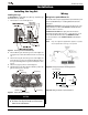
Direct Vent
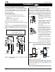
11”
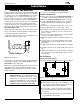
Ceiling box
MEXT-2
in position
11”
Figure 13c. Installing the ceiling box.
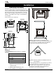
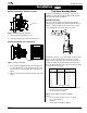
Figure 12. Vertical installation options. Left: straight vertical installa-
tion (no offsets).
B) Vertical (Through-The-Roof) Venting Option
When venting through the roof, use an FSTK04 Vent Kit. Additional
stove pipe or Montigo Standard Series vent components may be
used to increase the vent run, as long as the run still falls within the
limits set out in Figure 12.
Vertical Vent Requirements:
Vertical terminations (Part # MVTK-1) must be installed:
• minimum 2' above the highest point where the vent passes
through the roof
• minimum 6' from a mechanical air inlet
• minimum 18" from a parapet wall
Maximum vent height is 25 above the stove's flue collar.
(Note: Flame characteristics may change if the maximum vent height
is used.)
A maximum of two offsets (each offset has two 90° bends) may be
made. The total length of the offset(s) must not be more than 25% of
the vertical vent height, when measured from center to center of the
piping.
Example: Vertical vent height - 20 feet
25% of 20' = 5' max. offset allowed
2 - 2' offsets required = 4' offset
This vent configuration is acceptable.
Installing the Stove Pipe
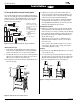
Ensure that the intended pathway for the venting is clear.Try to
position the stove midway between two joists to avoid having to cut
them. Determine the ceiling box location. Measure a minimum of 6
1/4" between the centre of the pathway and the back wall as shown
in figure 13a. For corner installations, measure 24 1/4" between the
back corner and the intended pathway as shown in figure 13b. This
will maintain the stove's minimum clear-
ances as shown on page 3. Cut and
frame an 11" x 11" hole in the ceiling and
roof as required.
Install the ceiling box as shown in Figure
13c. Ensure that there is at least 2"
clearance from the bottom of the box
to the ceiling. Fasten in place with 2
screws per side.
Slide the MEXT-2 down into position so
the male end protrudes into the room
below the ceiling box as shown in Fig-
ure 13c and secure it temporarily with an
MSPXT-7 support plate and ring.
Measure the flex pipe (FST08) and cut it
to the required length. Install the second
collar onto the end of the flex. Attach
one end of the flex to the inner collar
of the MEXT-2, and secure it with three
screws.
Slide the decorative ceiling plate about
two inches down from the end of the
top section of stove pipe. Install the top
stove pipe onto the outer collar of the MEXT-2. Now slide the decora-
tive ceiling plate up against the bottom of the ceiling box and secure it
with four screws. Install the first spacer spring by sliding it up over the
bottom of the stove pipe.
Now slide the slip section (Part # FST05) up over the flex, overlap-
ping the top section at least half its length to keep the pipe out of your
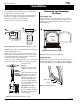
Figure 13b. Determine the ceiling box location for a corner instal-
lation. To ensure that a 10 1/2" clearance is maintaned
the centre of the flue should be 24 1/4" from the back
corner.