
Instruction manual

R720 & R820 Power Vent Indoor Gas Fireplace
Page 32
XG0772 - 100614
Appendix
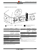
Appendix A: Power Vent Locations
For installation instructions on this termination see instruction guide
for the PVVEX510-300�
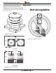
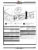
PVVEX510-300 Vertical Power Vent Detail
Front View
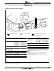
Not Acceptable
Side View
Fr
o
nt Vi
e
w
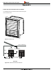
Top View
24”
24”
Wall
Wall
18”
40” [1016 mm]
18”
Min.
Wall
24”
[610 mm]
[610 mm]
[610 mm]
[457 mm]
Figure 24. PVVEX510-300
Figure 24a. PVVEX510-300 clearances
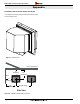
Figure 16b. PVVEX58-300 restrictions