
Instruction manual
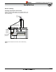

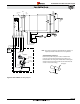
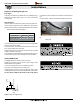
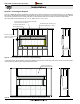
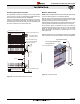
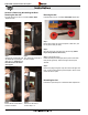
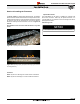


Figure 17. Gas Inlet Supply location.
Fuel Type
Verify that your replace is compatible with your available gas type.
Natural Gas or Propane shown by "N" or "L" in your model number
on rating plate�
Gas Pressure
Optimum appliance performance requires proper input pressures�
Gas line sizing requirements will be determined in ANSI Z221�3
National Fuel Gas Code in the USA and CAN/CGA B149 in Canada.
Pressure requirements (during operation):
The manifold outlet pressure is set from the factory to the appropriate
pressure but should be veried.
To check pressures, control valves have a provision to remove a 1/8”
N.PT. plug to be tted with a hose barb.
Montigo requires a service shut off valve be located in an accessible
location to isolate the gas supply�
Only install gas shut-off valves approved for use by the state, province,
or other governing body in which the replace is being installed.
GAS CONNECTION
See Figure 16 below for location of gas line access�
Flexible gas connectors must not exceed 3 feet in length, unless
allowable within local regulations�
Connect incoming gas line to the 1/2" Male NPT gas inlet.
Purge all air out of gas line before connecting port�
Check appliance connection, valve and valve train under normal
operating pressure with a commercially available leak check solution�
DO NOT USE A FLAME OF ANY KIND TO TEST FOR LEAKS�
Pressure Requirements
Gas Pressure Natural Gas Propane
Minimum Inlet Pressure 5�5" W�C� 11" W�C�
Manifold Pressure 3�5" W�C� 10" W�C�
Section 5: Installing the gas line
1
¾”
1/2” MPT gas
inlet
Figure 17a. Identifying the Gas Inlet and Combustion Air Switch
Sensor Line
Located next to the Gas Inlet is the Combustion Air Switch Sensor
Line�
Do NOT obstruct or alter the Combustion Air Switch Sensor Line�
R720 & R820 Power Vent Indoor Gas Fireplace
Page 24
XG0772 - 100614
Installation