
Instruction manual
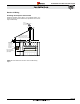

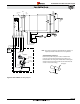
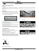
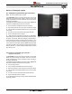
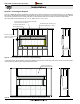
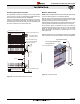
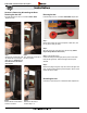
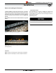


Figure 15a. (Control Panel Overview)
Figure 15b. R720* / R820* Control Module
Left-side View Right-side View
Figure 15c.
(Remote Switch Wire connection)
Wall Switch
Installing the Remote Switch
The R720* / R820* may be connected to a wall switch� The system
operates on a 24V AC� DO NOT connect this circuit to an external
power source�
The power cord from the power vent module plugs into the side of
this panel� The 20 foot low voltage wire is attached and connected
to this panel as well. Connect a single pole On/Off switch (Black and
White) to these two wires at a location of your choice, (See Installing
the Remote Switch).
Montigo supplies 20' of low voltage wire to the electrical control panel.
Connect the two wire harnesses to a standard single pole ON/OFF
switch to the location of your choice� You may extend these wires
up to 100' in length with a wire of equal quality.
Installations in Canada must be electrically grounded in accordance
with CSA C22�1 Canadian Electrical Code Part 1 and/or Local Codes.
Installations in the USA must be electrically grounded in accordance
with local codes or, in the absence of local codes, with the National
Electrical Code, ANSI/NFPA 70�
Installation of Electrical Supply
The R720* / R820* is supplied with an external electrical control
panel pre-wired by the factory� The control box is connected to the
replace with a 20 foot long control cable that will communicate with
the replace. The control panel should be located where it can be
accessed when the replace has been nished in.
Power Vent
Harness
LED Indicator
Fuse
115V
Power Supply
Wall Switch
Control
cable
115V
Outlet
Power Vent
Speed Control
Post Purge
Timer (3 min�)
Prepurge
Timer (1 min�)
Power
Vent Fuse
(5A)
Power Vent
Connector
Control
Panel Fuse
(
5A)
LED
Power
Indicator
Heat Sensor /
Conmustion Switch
NOTE: Ensure that you maintain a 1" clearance around the box�
R720 & R820 Power Vent Indoor Gas Fireplace
Page 22
XG0772 - 100614
Installation