
Instruction manual


R720 & R820 Power Vent Indoor Gas Fireplace
Page 21
XG0772 - 100614
Installation
Section 4: Wiring
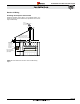
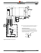
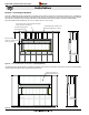
Figure 15.
R720* / R820* Series Control Box / Power Vent Wire Routing
Diagram
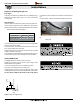
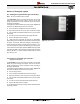
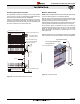
Installing the Fireplace Control Box
Install the Fireplace Control Box in an accessible location� The
location should be where maintenance, adjustments and service
may be made easily�
Control
Box
Horizontal
Po
wer Vent
Te
rmination
Vertica
l
Power Vent
Termination
Power cable
Installation
required for either Horizontal
or Vertical Termination Vent
115Va
c 60 Hz
supply from
Distribution P
anel
Wall Switch
Power
Vent
20 foot control
cable to replace
(standard)