
Instruction manual
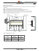


The following components and associated Montigo part numbers are for
installation of a roof or wall mounted Power Vent. Only use Montigo Vent
Components. Use of non-Montigo parts will VOID the warranty and may impede
operation of the replace.
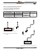
A - Termination PVHEX510-300 Wall Mount
5'/10'
PVHFL510-300 Flush Wall
Mount 5'/10'
PVVEX510-300 Roof Mount
5'/10'
B - Frame Kits EPVRRF (Roof Mount 5"/10")
EPVRWF (Wall Mount 5"/10")
C - Flex Sections RFL1 (12" f/f Section)
RFL2 (24" f/f Section)
RFL3 (36" f/f Section)
RFL4 (48" f/f Section)
RFL6 (72" f/f Section)
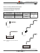
D - Rigid Sections RXT - 10 (10" f/f Section)
RXT - 20 (20" f/f Section)
REXT - 1 (12" f/m Section)
REXT - 2 (24" f/m Section)
REXT - 3 (36" f/m Section)
REXT - 4 (48" f/m Section)
REXT - 6 (72" f/m Section)
E - Elbows REL-90MM (m/m 90º Elbow)
REL-90FF ( f/f 90º Elbow)
REL-90FM ( f/m 90º Elbow)
REL-45FM ( f/m 45º Elbow)
F - Support Ring & Plate RSPXT-10
G - Firestop FS-10
H - Heat Shield RHS102
Connection and installation of the vent components should
adhere to the following guidelines:
Montigo recommends the use of a ex section for the nal pipe
connected directly to the replace offering greater exibility
of installation and absorption of movement�
Firestops must be installed as required by National & local
codes�
Montigo recommends that all exterior corners and joints be
sealed with exterior caulking� However, we encourage you
to consult your Building Envelope Engineer or Waterproong
Consultant for further recommendations�
Use any combination of rigid and ex pipe as required and in
any orientation (Male connectors can face in any direction)�
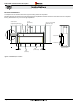
Flex sections may be stretched up to 50% of their total length
(e�g� a 24” section maybe stretched to 36”)�
Ensure the pipe ends male to female slide in a minimum of
1 1/2” of overlap.
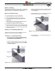
Connect all vent sections using a minimum of three sheet
metal screws on the outer pipe ue.
Ensure all horizontal runs are supported with a minimum of
3 supports per 10’ of venting�
When hanging/ supporting venting, ensure that 1” clearance
is maintained on sides and bottom of vent runs and 2” above
horizontal vent runs to any combustible material�
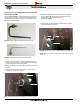
Rigid pipe may be cut less than half way from the female
end only�
Ensure when cutting sections of rigid pipe to maintain integrity
of internal supports�
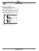
Place the springs, supplied with the pipe kit, between the
outer and inner pipes to keep the pipes separate and avoid
any possible hot spots�
IMPORTANT:
Please Refer to your Building Envelope
Engineer or Waterproong Consultant
for a review of ALL penetrations through
exterior walls or the roof�
R720 & R820 Power Vent Indoor Gas Fireplace
Page 19
XG0772 - 100614
Installation
Section 3-4: Venting components