Installation & Maintenance Manual R720 R820 R-Series Indoor Residential Fireplace WARNING DANGER Read and understand this manual. Improper installation, adjustment, alteration, service or maintenance can cause serious injury, property damage or even death. For assistance or additional information consult a qualified installer, service agency or the gas supplier. Do not store or use gasoline or any other flammable vapors and liquids in the vicinity of this or any other gas burning appliance.
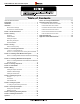
R720 & R820 Power Vent Indoor Gas Fireplace Instruction Manual Contents Table of Contents Section 10: Cleaning and Maintenance ���������������������������������������31 Safety Alerts �������������������������������������������������������������������������������������3 Appendix A: Power Vent Locations ���������������������������������������������32 Introduction ���������������������������������������������������������������������������������������3 PVVEX510-300 Vertical Power Vent Detail ���������
R720 & R820 Power Vent Indoor Gas Fireplace Safety Alert Key Safety Alerts With over 30 years of experience, Montigo is committed to providing you with a gas fireplace that is not only a beautiful addition to your space, but that is also designed and manufactured to the highest safety, reliability and engineering standards. We strongly encourage you to read and carefully follow the instructions laid out in this Installation, Operation and Maintenance Manual and retain it for your future reference.
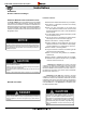
R720 & R820 Power Vent Indoor Gas Fireplace Installation Installation Section A: Before You Begin Installation Checklist IMPORTANT MESSAGE: SAVE THESE INSTRUCTIONS The R720* & R820* Power Vent fireplaces must be installed in accordance with these Instructions. Carefully read all the instructions in this manual first. Consult the Local Gas Branch to determine the need for a permit prior to starting the installation.
R720 & R820 Power Vent Indoor Gas Fireplace Installation Introduction to the R-Series Fireplace: The complete system will require a firebox, a power vent module, an electrical control panel, and a vent system. The appropriate vent system will connect the firebox to the power vent module and will be placed in a vertical or horizontal location. The R-Series fireplace is not a heat efficient fireplace and should not be used with a thermostat to heat your home.
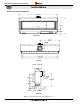
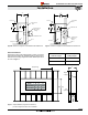
R720 & R820 Power Vent Indoor Gas Fireplace Installation Section 1: Product Dimensions Front View Top View Gas Inlet Combustion Air Switch Sensor Line Side View Figure 1. R720* Fireplace dimensions (Tolerance ± ⅛").
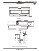
R720 & R820 Power Vent Indoor Gas Fireplace Installation 108 11/16" 18" 40 1/16" 97 1/8" Front View 54 5/16" 21 1/8" 24 7/16" REF 5 7/8" 3/8" 97 1/4" 101 9/16" Top View 15 1/8" 21 3/4" 4 7/8" 9 7/8" 18 1/8" 33 7/8" 10 13/16" 12 3/8" 3 7/16" REF 5 7/8" Gas Inlet Combustion Air Switch Sensor Line Side View Figure 1a. R820* Fireplace dimensions (Tolerance ± ⅛").
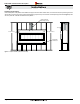
R720 & R820 Power Vent Indoor Gas Fireplace Installation Section 2: Framing Clearances: MODEL Top - Rear Vent † Top - Top Vent † Rear - Top Vent Rear - Rear Vent Sides Floor Mantel To ensure the fireplace operates safely, all models must maintain the following clearances: R720* 24 24 2 6 3 0 6 R820* 24 24 2 6 3 0 6 Wall framing 2” Min. † Note: Clearance from top of fireplace to a combustible ceiling within the fireplace enclosure.
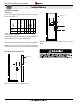
R720 & R820 Power Vent Indoor Gas Fireplace Installation 3 " 4 983 34" 863 38 Header Header Stud Wall Rear Stud Wall Rear 24" 610 8" 203 1 " 4 463 18 24" 610 Termination Mounting Flange PVHFL58-300 PVHEX58-300 Termination Mounting Flange Floor Fireplace Fireplace Figure 2b. Clearances for straight rear vented installation with PVHEX510-300. Floor Figure 2c. Clearances for straight rear vented installation with PVHFL510-300.
R720 & R820 Power Vent Indoor Gas Fireplace Installation Installing the Fireplace: Place the Fireplace on the platform and install the Vent pipe, and Power Vent module. Next, connect the Gas line, and provide a gas service shut-off valve; according to local gas codes. Before fastening in place line up the front face of the fireplace (top and bottom Figure 3). then secure in place with 1/4"bolts and washers to the platform.
R720 & R820 Power Vent Indoor Gas Fireplace Installation Back framing the Fireplace NOTE: Maintain a 1" clearance around the throat (projection at the front of the fireplace that holds the glass door) when installing 2x4s for back framing. Step 1). Cut and install one 2x4 to fit horizontally under the fireplace throat. Step 2). Cut and install required quantity of short filler 2x4's to fit vertically under the horizontal piece. Step 3). Cut and install four vertical 2x4's.
R720 & R820 Power Vent Indoor Gas Fireplace Installation Recessed Installation: This fireplace can be recessed into the floor to get the viewing area as low as possible. Maintain a minimum of 6" clearance from the Header bottom of glass to completed floor. Minimum clearance can be reduced to 3" for uncarpeted Picture of Non combustible flooring. Discolouration may occur due to high temperatures. Steel header (supplied by Montigo) 2x4 (horizontal) 2-pcs 2 x 4 (vertical) Both Sides Typ.
R720 & R820 Power Vent Indoor Gas Fireplace Installation Section 3: Venting Montigo supplies a variety of power venting options. The location of the power vent should be selected and laid out to provide the most efficient possible run to an external wall or through the roof. 3. Install the removed Rear flue cover (5" and 10") to the Top Vent outlet. Fasten the cover with included hardware, as . shown in Figure 7a. Notes For Planning Venting: 4.
R720 & R820 Power Vent Indoor Gas Fireplace Installation Section 3-1-2: Converting the Pressure Sensing Tube and Air Baffle When the R720* / R820* is converted from Top Vent to Rear Vent, the pressure sensing tube must be removed and replaced with supplied Rear Vent pressure sensing tube and air baffle must be relocated as described below. 3. Position the supplied Rear Vent pressure sensing tube as shown in Figure 9a. Hand tighten the compression nut by hand and then a half-turn with a wrench.
R720 & R820 Power Vent Indoor Gas Fireplace Installation Section 3-2: Installing a Roof Mounted Vent System This section applies to installations where the most efficient vent run is through the roof. Refer to Appendix A - Power Vent locations, to ensure the planned Power vent location is acceptable. Refer to the table below for vent run requirements.
R720 & R820 Power Vent Indoor Gas Fireplace Installation D** D** Figure 10b. Multi-Elbow with downward vent run, Top or Rear Vent, Roof mounted power vent. Section 3-2-1: Installing Roof Mounted Power Vent Module - PVVEX510-300 Note: See Power Vent manual for installation instructions. Note: See Appendix A for clearance to exterior structures.
R720 & R820 Power Vent Indoor Gas Fireplace Installation Section 3-3: Installing a Wall Mounted Vent System This section applies to installations where the shortest possible vent run is through the wall. Refer to Appendix A - Power Vent locations, to ensure the planned Power vent location is acceptable. Refer to the table below for vent run requirements.
R720 & R820 Power Vent Indoor Gas Fireplace Installation D** D** Figure 12b. Multi-Elbow with downward vent run, Top or Rear Vent, Wall mounted power vent. Section 3-3-1: Installing Wall Mounted Power Vent Modules - PVHEX510-300 and PVHFL510-300 Note: See Power Vent manual for installation instructions. Note: See Appendix A for clearance to exterior structures.
R720 & R820 Power Vent Indoor Gas Fireplace Installation Section 3-4: Venting components The following components and associated Montigo part numbers are for installation of a roof or wall mounted Power Vent. Only use Montigo Vent Components. Use of non-Montigo parts will VOID the warranty and may impede operation of the fireplace.
R720 & R820 Power Vent Indoor Gas Fireplace Installation Section 3-5: Heat Shields Installing a Wall Mounted RHS102 Heat shield The RHS102 Heat shield must be used if vent pipe passes through a wall or ceiling within 6' of the unit. To install the RHS102, Slide the Inner Section over the vent pipe that will connect to the fireplace. Then fasten the vent pipe to the back of the fireplace with a minimum of three sheet metal screws. From the outside slide the RHS102 outer section on.
R720 & R820 Power Vent Indoor Gas Fireplace Installation Section 4: Wiring Installing the Fireplace Control Box Install the Fireplace Control Box in an accessible location. The location should be where maintenance, adjustments and service may be made easily.
R720 & R820 Power Vent Indoor Gas Fireplace Installation Installation of Electrical Supply The R720* / R820* is supplied with an external electrical control panel pre-wired by the factory. The control box is connected to the fireplace with a 20 foot long control cable that will communicate with the fireplace. The control panel should be located where it can be accessed when the fireplace has been finished in. The power cord from the power vent module plugs into the side of this panel.
R720 & R820 Power Vent Indoor Gas Fireplace Installation ELECTRICAL CONTROL PANEL Flue Gas Combustion Air Fuse Wall Switch R1 R2 R3 Pre-Purge Timer 110 Volts 60Hz 5A 115 Light R1 R2 R3 Brown Blue Orange Blue Black Yellow Yellow Plug White Black White 4 Blue PV Speed Controller 5 Yellow Brown Red Blue Black Gas Valve Blk/Wht Wht/Blk White Wall Switch 1 2 Post Purge 3 Timer PV Note: If any of the original wire supplied with the appliance is replaced, it must be with the sam
R720 & R820 Power Vent Indoor Gas Fireplace Installation Section 5: Installing the gas line Fuel Type Verify that your fireplace is compatible with your available gas type. Natural Gas or Propane shown by "N" or "L" in your model number on rating plate. Located next to the Gas Inlet is the Combustion Air Switch Sensor Line. Do NOT obstruct or alter the Combustion Air Switch Sensor Line. Gas Pressure Optimum appliance performance requires proper input pressures.
R720 & R820 Power Vent Indoor Gas Fireplace Installation Section 6: Testing the system 6-1: Testing the system before gas connection Note: No gas is needed to test the system The R720*/R820* Control and Power Vent System can be safely tested prior to finish framing the Fireplace. This test can be done quickly and efficiently to ensure all systems function according to the design specifications.
R720 & R820 Power Vent Indoor Gas Fireplace Installation Section 7: Finishing the fireplace As shown in Figure 19; Install the supplied Non-combustible cement board to overlap the new Horizontal & Vertical 2 x 4's, See Figure 5. Place the Non-combustible wall board above the fireplace throat, allowing 1/8" clearance from the rim above the fireplace opening. Pre-drill the board with 1/8" drill and secure to framing with Nails, use flat heat sheet metal screws to fasten the board to the metal header.
R720 & R820 Power Vent Indoor Gas Fireplace Installation Finishing Around the Fireplace Mantels & Surrounds Non-combustible mantels and mouldings may be safely installed over the top and on the front of the fireplace provided that they do not project beyond shaded area shown in Figure 20. NOTE: National Canadian Gas Association mantel test requirements are for fire hazard prevention to combustible materials.
R720 & R820 Power Vent Indoor Gas Fireplace Installation Section 8: Removing & Installing the Door Removing the door trim: Follow the steps below to remove, or install the R720* / R820* fireplace door trim. Removing the door: Follow the steps to remove, or install the R720*/R820* fireplace door. Step 1: Remove glass suction cups from box and place on Glass door. (The tool may not be exactly as shown). Step 2: Place the suction cups on the glass door, spaced evenly.
R720 & R820 Power Vent Indoor Gas Fireplace Installation Section 9: Installing the Firestones Optional River Rocks The R720* / R820* is supplied with glass firestones. To install the firestones remove the trim and door as shown in the previous section. Follow these instructions to ensure all parts are removed or replaced as required. Once the trim and glass door is removed, place the firestones randomly around the burners as shown in Figures 22 and 22a.
R720 & R820 Power Vent Indoor Gas Fireplace Operation Operation WARNING If the information in these instructions is not followed exactly, a fire or explosion may result causing property damage, personal injury or death. Startup Sequence: 1) Turn the wall switch ON 2) The combustion air switch relay will light up and the blowers . will start. Within 10 seconds the flue gas air switch will turn on. 3) The glow plugs will start to glow 45 - 60 seconds after the pre-purge period.
R720 & R820 Power Vent Indoor Gas Fireplace Maintenance Section 10: Cleaning and Maintenance Cleaning General ■ Have the fireplace and installation inspected yearly. The inspection must include, but is not limited to, the following: • A visual check of the entire vent system and termination. • An inspection of the door gaskets to ensure a proper seal. • An inspection of the burner, vent run, and primary air openings. • An inspection of the gas valve, gas components, and pilot flame.
R720 & R820 Power Vent Indoor Gas Fireplace Appendix A: Power Vent Locations Appendix PV VEX510-300 Vertical Power Vent Detail For installation instructions on this termination see instruction guide for the PVVEX510-300. Not Acceptable Front View Figure 24. PVVEX510-300 Side View Wall [610 mm] 24” Figure 16b. PVVEX58-300 restrictions Wall 24” [610 mm] Top View 24” [610 mm] 40” [1016 mm] Wall 18” 18” Min. [457 mm] Front View Figure 24a.
R720 & R820 Power Vent Indoor Gas Fireplace Appendix PVVEX58-300 PVVEX510-300 Power Vent Locations E INSID ETAIL ER D CORN G v H A D E V B B B C FIXED ED CLOS v V L F ABLE OPER v ABLE OPER v FIXED ED CLOS v I X M v X K v B A J B V VENTER TERMINAL Canadian Installations X AIR SUPPLY INLET 1 US Installations 2 A= Clearance above grade, veranda, porch, deck, or balcony 12 in (30 cm) 12 in (30 cm) B= Clearance to window or door that may be opened 6 in (15 cm) for appliances
R720 & R820 Power Vent Indoor Gas Fireplace Appendix PVHEX510-300 Horizontal Power Vent Detail For installation instructions on this termination see instruction guide for the PVHEX510-300. Figure 17. PVHEX510-300 Eaves / Overhang 6” [152mm] Wal l 14” [355mm] 6” [152mm] 16” [406mm] 32” [813mm] Side View Figure 24b.
R720 & R820 Power Vent Indoor Gas Fireplace Appendix PVHEX58-300 Power Vent Locations PVHEX510-300 E INSID ETAIL ER D CORN G v H A D E V B L V F B B C v FIXED ED CLOS v OPER FIXED ED CLOS BLE v A OPER ABLE B I M X v X v A v K J B V VENTER TERMINAL Canadian Installations X AIR SUPPLY INLET 1 US Installations 2 A= Clearance above grade, veranda, porch, deck, or balcony 12 in (30 cm) 12 in (30 cm) B= Clearance to window or door that may be opened 6 in (15 cm) for appli
R720 & R820 Power Vent Indoor Gas Fireplace Appendix PV HFL510-300 Horizontal Power Vent Detail For installation instructions on this termination see instruction guide for the PVHFL510-300. Figure 18. PVHFL510-300 Eaves / Overhang 15” [152mm] 24” [610mm] Wall 15” [152mm] 24½” [622mm] 24” [610mm] Front View Figure 24d.
R720 & R820 Power Vent Indoor Gas Fireplace Appendix PVHFL510-300 Power Vent Locations PVHEX58-300 E INSID ETAIL ER D N R O C G v H A D E V B L V F B B C v FIXED ED CLOS v OPER FIXED ED CLOS ABLE v OPER ABLE B I M X v X v A v K J B V VENTER TERMINAL Canadian Installations X AIR SUPPLY INLET 1 US Installations 2 A= Clearance above grade, veranda, porch, deck, or balcony 12 in (30 cm) 12 in (30 cm) B= Clearance to window or door that may be opened 6 in (15 cm) for ap
R720 & R820 Power Vent Indoor Gas Fireplace Appendix Appendix B: Warranty The Warranty The Companies warrants the Montigo Gas Appliance to be free from defects in materials and workmanship at the time of manufacture. On the Montigo fireplace, there is a ten-year warranty on the firebox and its components, a five-year warranty on the main burner and pilot burner, and a one-year warranty on the gas control valve, fibre logs and Power Vent Module.
R720 & R820 Power Vent Indoor Gas Fireplace Appendix Appendix C: State of Massachusetts Amendment (Gas Fireplace / Equipment sold in the State of Massachusetts) 5.08: Modifications to NFPA-54, Chapter 10 (1) Revise NFPA-54 section 10.5.4.
R720 - R820 Single Sided Gas Fireplace XG0772 -100614