
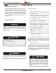
Specifications

Frame in the enclosure for the unit with framing materials, see
NOTE: When constructing the framed opening, please ensure there is
access to install the gas line when the unit is installed. See Figure 16.
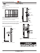
Clearances:
To ensure the replace operates safely, all models must maintain
the following clearances:
†
†
† Note: Clearance from top of replace to a combustible ceiling
within the replace enclosure.
Unprotected combustible walls which are perpendicular to the replace
opening must maintain 6" clearance, see gure 20.
C
learances for rear vented installation with elbow.
C
learances for top or rear vented installation, straight vent run or with
elbow(s).
Clearances for straight rear vented installation.
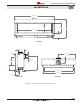
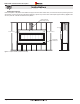
Exterior
Sheating
Exterior
Finishing
M
ate
ri
a
l
Exterior wall
framing
Exterior
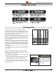
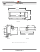
EPVRW
Power Vent
EPVRWF rough
-in Frame
8” Min.
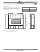
Venting Clearance Requirements:
Wall framing
14” Min.
Wall framing
2” Min.
Page 8
XG0771 - 040513
Section 2: Framing