
Specifications
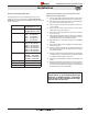
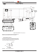
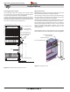

LED Indicators
I
f the red LED is illuminated (beside the fuse) you have power
to the panel.
If no LED, check fuse and replace with equally rated fuse.
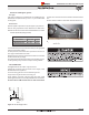
T
he power vent motor should start running and time out after
three to four minutes.
Turn the wall switch to the on position.
O
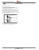
bserve the combustion air switch, an LED will light up immediately.
After approximately 1 minute, the ue gas switch LED will light and
the Hot Surface Ignitor will glow RED. This conrms the control
system operation.
T
he control panel is supplied with a power cord plug in.
Plug it into a extension cord or any other 110 Volt power supply.
Note: No gas is needed to test the system
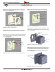
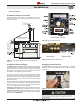
The R520* / R620* Control and Power Vent System can be safely
tested prior to nish framing the Fireplace. This test can be done
quickly and efciently to ensure all systems function according to
the design specications.
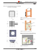
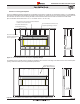
The replace should be installed on the rough-in frame, Figure 3 with
the Power Vent Module and the Vent run connected.
Section 6: Testing the system
Flue Gas
Switch LED
Combustion Air
Switch LED
Page 28
XG0771 - 040513