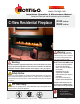
fire feature www.montigo.com Installation Operation & Maintenance Manual Check local codes and read all instructions prior to installation. C-View Residential Fireplace BF-Series SS Gas Fireplace R520 Indoor R620 Indoor Warning: If the information in these instructions is not followed exactly, a fire or explosion may result causing property damage, personal injury or death.
C-View Residential R520-R620 Series Indoor Gas Fireplace fire feature Warning: Read this manual before installing, operating or troubleshooting this appliance. Please retain this owner's manual for future reference. Congratulations! Congratulations on selecting a FireFeature gas fireplace, an elegant and well designed gas fireplace built to your specifications. The FireFeature gas fireplace you have selected is designed to provide the utmost in safety, reliability, and engineering standards.
C-View Residential R520-R620 Series Indoor Gas Fireplace fire feature Introduction Thank You for choosing a FireFeature Gas Fireplace. The C-View Residential Fireplace is a linear burner power vented fireplace. The R520 and R620 uses Montigo's 5”/10” Power Vent System. This venting systems are ideal for extremely long or difficult venting runs. The R520 is rated for Natural Gas at 80,000 BTU/H (23.2 Kilowatts) Input, and Propane at 65,000 BTU/H (18.9 Kilowatts).
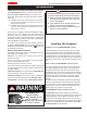
C-View Residential R520-R620 Series Indoor Gas Fireplace fire feature Installation WARNING! WARNING The C-View Residential unit is a power vented fireplace system. Under no circumstances can this model be installed without a power vent module. For regular Horizontal vent installation use model EPVRW with the rough-in kit model EPVRWF. For regular Vertical installation use model EPVRR with a rough-in kit model EPVRRF.
C-View Residential R520-R620 Series Indoor Gas Fireplace fire feature Installation Vent Installation Before installing the the rough-in kit on your roof or wall install the electrical cord model EPVH-10 to model EPVH-100 and connect it to the electrical control panel that was supplied with the fireplace. Do not attach the electrical wire to the exterior of the vent.The vent will get hot and may damage the wire.
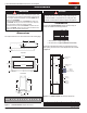
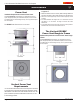
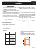
C-View Residential R520-R620 Series Indoor Gas Fireplace fire feature Installation The Vertical EPVRR Power Vent Installation Requirements for Vertical Power Venter The C-View Residential Series fireplace use a Designated coaxial vent system designed specifically for the Residential fireplace, and Use of other non-certified parts will void the Montigo warranty, and may impede the operation of the fireplace. The EPVRR Power Vent dimensions are show below.
C-View Residential R520-R620 Series Indoor Gas Fireplace fire feature Installation Available EPVRR Vertical Vent Components Installing the Vertical EPVRR Power Vent Selecting A Termination Location Before installing the termination or venting, check to ensure the planned termination location is acceptable and meets basic requirements shown in Appendix A ( Termination Locations). 14 1/2” 14 1/2” Installing the Residential’s Terminations with Frame 1.
C-View Residential R520-R620 Series Indoor Gas Fireplace fire feature Installation Step 5. Power Vent Rough-in Kit Install the Power Vent, Roof-top Stainless steel cover over the Installed Rough-in Kit. (You can see the Electrical harness connector in the top right corner). Electrical Harness Connector Location Electrical Harness from Power Vent Inset Electrical Harness Figure 4e. Figure 4f. Step 6. Figure 4b.
C-View Residential R520-R620 Series Indoor Gas Fireplace fire feature Installation Front View Stainless Steel Fasteners The Horizontal EPVRWF Power Vent Rough-in Frame Installation Requirements for Horizontal Power Venter Rough-in Frame. Figure 4h. (Installed Power Vent Module) Step 8.
C-View Residential R520-R620 Series Indoor Gas Fireplace fire feature Installation Horizontal Power Vent Requirements It is recommended that the External Power Vent System be used with a gas fireplace that is equipped with HSI. When installing the venting, the installation must adhere to the Vent Installation Section in these Instructions, as well as the following guidelines: Ensure that the planned termination location is acceptable as shown in Appendix A. ■ Maximum allowed vent run is 100 feet.
C-View Residential R520-R620 Series Indoor Gas Fireplace fire feature Installation Step 2. Step 5. Insert the Power Vent Rough-in Box as shown in Figure 5a. Fasten the Box securely in place with Screws or nails, Figure 5a. Apply exterior sheathing and finishing, if required. (Figure 4a). Securely fasten the bottom Collar pan into the Rough-in frame using the existing hardware, (4-pcs). Tighten the Strain Relief nut onto Strain relief fitting. Step 6.
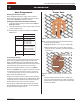
C-View Residential R520-R620 Series Indoor Gas Fireplace fire feature Installation Communication Harness. 5” Inner Flue Collar, Typ. All models (with gasket) TOP of Power Vent, (Note Quantity of louvers). 10” Outer Flue Collar, R520, R620 (with gasket) 5” Flue Cover Plate, Typ. All models (with gasket) Note louver direction 10” Flue Cover Plate, Typ. R520, R620 (with gasket) Figure 5f. (Installation of Power Vent communication harness) Step 9. Install the Power Vent.
C-View Residential R520-R620 Series Indoor Gas Fireplace fire feature Installation Note: No gas is needed to prove the system. The control panel is supplied with a power cord plug in. Plug it into a extension cord or any other 110 Volt power supply.
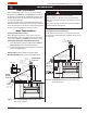
C-View Residential R520-R620 Series Indoor Gas Fireplace fire feature Installation Step 1. To ensure your glass viewing area is at the optimum height, follow the Example below, Figure 16. Example: If you wish to have the bottom edge of the glass to be 24", the top of the platform will be 13". This dimension takes in account the height of the platform, plywood and adequate clearances. U Q (Opening) Drywall or Equiv.
C-View Residential R520-R620 Series Indoor Gas Fireplace fire feature Installation combustibles), Figure 16b. Next, cut four vertical 2 x 4's to install between the Upper and Lower Horizontal 2 x 4's, (2-pcs either side). (Ensure these are placed the required 1" clearance to combustibles). Cut the top 2 x 4 (horizontal) to fit between the vertical 2 x 4's (iether side of fireplace) as shown. Last, install the Supplied Steel Header 1" above the fireplace throat.
C-View Residential R520-R620 Series Indoor Gas Fireplace fire feature Installation Step 5. As shown in Figure 6d; Cut standard Gyproc / Drywall board to complete the installation of the surround. Fit the edge of the board to the rim around the fireplace opening. Fasten the board in place using standard drywall screws. Wall board / Gyproc or Equiv. (Bottom & Sides) Figure 16d. Fireplace installation (Cut the remainder of Gyproc / Wall board to complete the fireplace surround).
C-View Residential R520-R620 Series Indoor Gas Fireplace fire feature Installation Installation Of Electrical Supply The C-View Residential Fireplace is supplied with an external electrical Control Panel pre-wired by the factory. The power control box is connected to the fireplace with a 20 foot long 6 conductor cable that will communicate with the fireplace.The control panel should be located in a location that would be assessable when the fireplace in finished.
C-View Residential R520-R620 Series Indoor Gas Fireplace fire feature Installation WARNING! If you do not follow these instructions exactly, a fire or explosion may result causing property damage, personal injury or loss of life. NC Gas Valve 1 LV Wall Switch 7 8 Gnd Green 6 Brn 5 Blu 4 Red 3 Blk / Wht 2 Wht / Blk Wht / Blk 1 Blk / Wht Pre-purge Time-On delay Post-purge Module NO Combustion Flue Gas Air Switch Switch Fireplace Figure 21.
C-View Residential R520-R620 Series Indoor Gas Fireplace fire feature Operation If you do not follow these instructions exactly, a fire or explosion may result causing property damage, personal injury or loss of life. WARNING! Startup Sequence: A. Purge all air out of the gas supply line to the fireplace system and ensure that the supply pressure is not in excess of 12" WC. B. Plug the electrical control panel into the power outlet.
C-View Residential R520-R620 Series Indoor Gas Fireplace fire feature Maintenance Removing and Installing the Door trim and Door Removing the door trim: Removing the door: Follow the (4) four steps to remove, or install the C-View Residential fireplace door. Follow the (4) four simple steps below to remove, or install the CView Residential fireplace door trim. Step 1: Remove glass suction cups from box and place on Glass door. (The tool may not be exactly as shown).
C-View Residential R520-R620 Series Indoor Gas Fireplace fire feature Maintenance Installing the C-View Residential Glass Beads and Optional River Rocks The C-View Residential fireplaces have the option of installing the optional cultured rocks or designer glass beads. As described below for Natural Gas and L.P. Note: The designer beads or cultured rocks cannot cover the burners. Doing so produces an undesireable / uneven flame pattern, and eventual sooting.
C-View Residential R520-R620 Series Indoor Gas Fireplace fire feature Maintenance Troubleshooting CAUTION! Fireplace gas control must be in the “OFF” position and pilot and main burners extinguished when cleaning appliance with a vacuum. Doors can get very hot. Handle only when cool. General Have the fireplace installation inspected yearly, including a visual check of the vent system, the burner and the pilot flame.
C-View Residential R520-R620 Series Indoor Gas Fireplace fire feature Maintenance Troubleshooting the Power Vent System: 1. Plug the power cord into a 110 Volt outlet. 2. The red LED will indicate that you have power. 3. The power vent module will run for three minutes and then it will time out. 4. Turn the wall switch to the "ON" position. 5. The left LED will light up, the power vent module will start running. 6.
C-View Residential R520-R620 Series Indoor Gas Fireplace fire feature Warranty Montigo - Lifetime Limited Warranty The Warranty The Companies warrants the Montigo Gas Appliance to be free from defects in materials and workmanship at the time of manufacture. On the Montigo, there is a ten-year warranty on the firebox and its components, a five-year warranty on the main burner, and a one-year warranty on the pilot burner, gas control valve and fibre logs.
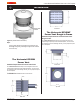
C-View Residential R520-R620 Series Indoor Gas Fireplace fire feature Appendix A - Powervent Locations The Vertical EPVRR Power Vent The Horizontal EPVRW Power Vent Wall 30” Min. Wall Eaves / Overhang Wall 30” Min. 30”Min. Top View [R] 24”Min. 30”Min. Front View [F] & [G] Wall 18” 18” Min. Front View [V] Part No.
C-View Residential R520-R620 Series Indoor Gas Fireplace fire feature Appendix A - Powervent Locations A = clearance to the termination frame above grade, veranda, porch, deck, or balcony [30 inches (75 cm) minimum] N= B = clearance to door, or sides and top of window, that may be opened [30 inches (75 cm) minimum for appliances.
C-View Residential R520-R620 Series Indoor Gas Fireplace fire feature Appendix B State of Massachusetts Amendment (Gas Fireplace / Equipment sold in the State of Massachusetts) 5.08: Modifications to NFPA-54, Chapter 10 (1) Revise NFPA-54 section 10.5.4.
fire feature XG0771 - 010610 Canadian Heating Products Inc. Langley, BC V4W 4A1 Montigo Del Ray Corp.