
Owner`s manual


Page 9
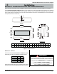
R520-ST & R620-ST Power Vent Indoor Gas Fireplace
Part No. XG0773 - 032211
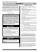
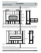
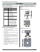
Figure 3a. Multi-elbow Venting Installations.
Multi-Elbow Installations
Multi-elbow installations are possible up to a maximum of six 90°
elbows.
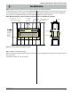
Figure 3b. Downward Venting Installations.
Downward Vertical Venting
Note: The downward vent run must not exceed 6' of vent run.
Installation
Max V1 + H1 + D + H2 + V3
Max Elbows
40’ feet
six 90
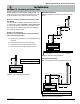
Section 3: Installing the Power Vent
Montigo supplies a variety of power venting options.
The
location of the power vent should be selected and laid out to provide
the shortest possible run to an external wall or through the roof.
Section 3-1: Installing a Roof Mounted Vertical Exterior Power
Vent (EPVRR)
This section applies to installations where the shortest possible vent
run is through the roof. Refer to Appendix A - Power Vent locations,
to ensure the planned Power vent location is acceptable. Once the
vent location has been established, please refer to the appropriate
section below for installation details.
Section 3-1-1: Venting Layout
Selection of components and details of venting lay out should
adhere to the following guidelines:
Ensure there is a minimum run of 2’ of straight pipe before the
power vent.
Ensure the maximum vent run does not exceed 80’.
Ensure the number of 90° elbows does not exceed 6.
Ensure the number of 45° elbows does not exceed 12.
Elbow 1
Elbow 2
Elbow 3
Elbow
H1
V1
D = 6’ foot
MAX
V3
H2
Elbow 4
Figure 3. Typical straight Venting Installations.
Max V Max Elbows
120’ feet
N/A
,
Max V1 + H1 + V2 + H2 + V3 Max Elbows
100’ feet
six 90
Elbow 1
Elbow 2
Elbow 3
Elbow 5
Elbow 4
H2
H1
V1
V2
V3