
Owner`s manual


Page 6
R520-ST & R620-ST Power Vent Indoor Gas Fireplace
Part No. XG0773 - 032211
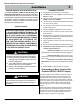
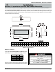
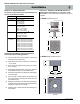
Q (Opening) both sides typical
R (Opening)
both sides typical
U
3/4”
Plywood
Platform
Section 2: Framing
Installation
Figure 2. Fireplace installation, (Rough Frame-In dimensions) Both Sides are Typical.
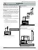
Step 2. Once the replace is placed on the platform, ensure there is access to install the vent pipe, and inline power vent module if applicable
and the gas line. Note the gas line connection location and room to provide a gas service shut-off valve; according to local gas codes. Before
fastening in place line up the front face and rear face of the replace (top and botttom), Figure 2a. then secure in place with 1/4" wood screws.
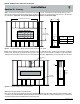
Step 1. You will need to construct a platform in the framing for the replace to sit on. To determine how high to build the platform you must
determine the how high you would like the bottom edge of your glass viewing area to be. The bottom edge of the glass sits 15 1/8" above the
top of the platform. Please note: The top of the platform may not exceed 24" in a room with 8' ceilings.
Figure 2a. Fireplace installation, (Inlet Gas & Power Vent) .
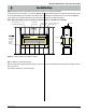
Step 3. Back-framing the Fireplace (Typical Both sides).
Back -frame in the replace using typical framing practice, see Figure 2b on both sides and meeting clearance requirements shown on page
5. Install the non-combustible headers supplied by Montigo above the replace on both sides as required to attach facing. For cleanest nish
ensure that the facing material is installed ush to the glass viewing area.
1/2”
Supply Gas
connection
Inta
k
e / Ex
h
aust
Venting
Both
Sides
Typ
Max Platform
Ht.
Ceiling
Ht
24" 8'
48" 10'
Framing Dimensions
Model# Q R U
R-Series R520 80¾" 50" 23¾"
R-Series R620 92¾" 50" 23¾"