
Owner`s manual


Page 25
R520-ST & R620-ST Power Vent Indoor Gas Fireplace
Part No. XG0773 - 032211
Maintenance
General
Have the replace and installation inspected yearly. The inspection
must include, but is not limited to, the following:
• A visual check of the entire vent system and termination.
• An inspection of the explosion relief appers and the door
gasketing to ensure a proper seal.
• An inspection of the burner, venturi, and primary air openings.
• An inspection of the gas valve, gas components, and pilot ame.
For your convenience a 1/8" manifold pressure tap is supplied
on the gas valve for a test gauge connection.
• Ensure proper log placement as per this manual.
• Inspection of all optional equipment; fans, thermostats, etc.
For Natural Gas this appliance requires a minimum inlet pressure
of 5.5" W.C. and a manifold pressure of 3.5" W.C.
For Propane Gas this appliance requires a minimum inlet pressure
of 11" W.C. and a manifold pressure of 10" W.C.
Always keep the replace area clear and free of combustible materials,
as well as gasoline and other ammable vapors and liquids.
Do not use this appliance if any part has been under water. Immediately
call a qualied service technician to inspect the appliance and to
replace any part of the control system and any gas control which
has been under water.
Cleaning
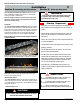
When the replace is rst activated, there may be some smoking and
a visible lm may be left on the glass. This is a normal condition, and is
the result of burning of protective coatings on new metal.
Glass must be cleaned periodically to remove any lm (which is
a normal by-product of combustion) which may be visible. Film
can easily be removed by removing the door, as shown on Page
23. Handle the door carefully, and clean it with non-abrasive glass
cleaners. One of the most effective products is Kel Kem.
Silicone seals on inner door during initial ring will "off gas", leaving
a visual deposit of a white substance on combustion chamber walls.
This can easily be removed using normal household products.
Use a vacuum cleaner or whisk broom to keep the control
compartment, burner, and rebox free from dust and lint.
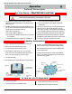
Lighting Instructions
See pages 23 and 24.
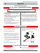
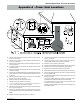
Figure 20. Honeywell SV9501 gas valve.
Bk
R
W
Honeywell (Q3450)
Pilot Assembly
Pilot Electrical
Harness Connector
Honeywell Gas
Control (SV9501M)
Gas Control
Connector
Gas Control Valve (Honeywell HSI)