
Owner`s manual


Page 22
R520-ST & R620-ST Power Vent Indoor Gas Fireplace
Part No. XG0773 - 032211
DO NOT OPERATE THIS FIREPLACE WITHOUT THE GLASS
DOOR OR WITH A BROKEN GLASS DOOR.
CAUTION!
Installation
The C-View Residential R520-ST & R620-ST replace have the
option of installing the supplied glass Firestones or other optional
colored glass media, or cultured rocks.
Note: The designer Firestones or cultured rocks cannot cover
the burners, doing so produces an undesirable / uneven ame
pattern and eventual sooting.
Firestones
The C-View Residential R520-ST & R620-ST replace are supplied
with a quantity of Glass Firestones. To install the Firestones remove
the Door and trim as shown in the previous Instruction. Follow these
instructions to ensure all parts are removed or replaced as required.
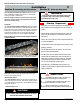
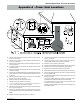
Once the Trim and glass doors are removed place the restones
randomly around the burners as shown in Figures 19 and 19a.
Note: DO NOT cover the burners with designer Firestones
or Optional Rocks.
Figure 19. Completed glass Firestone installation. (Note: place glass
Firestones on top of mesh pilot cover to complete the installation.
Figure 19a. Operating Propane gas replace with designer glass
Firestones surrounding burner tray.
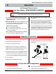
Optional River Rocks
The C-View Residential replace has the option of installing the cul-
tured rocks which mimic real stone. These may be spaced at random,
or in a visual pattern of your preference. See the Montigo web site for
photographs and ideas.
www.montigo.com
Section 8:
Installing the Firestones
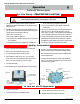
Startup Sequence:
A. Purge all air out of the gas supply line to the replace sys-
tem and ensure that the supply pressure is not in excess of
12" WC.
B. Plug the electrical control panel into the power outlet. (The
power vent will start and run for about three minutes and
then turn off.
Caution: Do not turn OFF the power to this panel at this time
to operate the replace
1. Turn the speed control on the right side of the panel to a low
positing ( clockwise ).
2. Turn the wall switch to the "On" position. The LED on the
left of the panel should illuminate.
3. Turn the speed up on the speed control knob very slowly
until the right LED is illuminated. Note: There will be a 1/2
minute Time-On delay, then burner will re up. This Initial
setting will produce the most attractive looking re. How-
ever, You may increase the speed if desired.
4. If the right LED is not illuminated when the power vent
module is running it will be a signal that the combustion air
supply is inadequate.
This replace has been set up at the factory for a
determined air volume though the venting system.
This replace will not operate unless the correct
air movement is detected by our control system..
Please consulted with your contact person at
Montigo should you have any problems with your start up.
CAUTION!
WARNING!
If you do not follow these instructions exactly, a re
or explosion may result causing property damage,
personal injury or loss of life.
Section 9: Start-up Sequence