
Owner`s manual

Page 17
R520-ST & R620-ST Power Vent Indoor Gas Fireplace
Part No. XG0773 - 032211
Installation
Section 4: Wiring
Installation
CAUTION!
The valve has a 1/2 minute Time-On Delay to clear All possible
build up of burned gas within the System.
After this Time-On Delay the replace will proceed with the Initi-
ated Start-Up Sequence has completed.
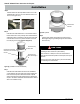
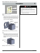
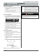
Figure 9. (Control Panel Overview)
Gas Control
Wiring & Air
Proving
Switch
Vent Speed
Control
Terminal Block
Power Vent
Motor
Indicator
light
Fuse
Ignitor
operation
Lights
110V Power
Supply
Wall
Switch
Pre-purge
Module
Post-purge
Module
Installation Of Electrical Supply
The C-View Residential R520-ST & R620-ST Fireplaces are sup-
plied with an external electrical Control Panel pre-wired by the factory.
The power control box is connected to the replace with a 20 foot
long 6 conductor cable that will communicate with the replace.The
control panel should be located in a location that would be accessible
when the replace in nished.
The power cord from the power vent module pugs into the side of this
panel. A 20 foot low voltage wire is attached and connected to this
panel as well. Connect a single pole On/Off switch (Black and White)
to these two wires at a location of your choice, (See Installing the
Remote Switch).
Installations in Canada must be electrically grounded in accordance
with CSA C22.1 Canadian Electrical Code Part 1 and/or Local Codes.
Installations in the USA must be electrically grounded in accord-
ance with local codes or, in the absence of local codes, with the
National Electrical Code, ANSI/NFPA 70-1987.
Installing The Remote Switch
The C-View Residential R520-ST & R620-ST Fireplaces may be
connected to a wall switch or a hand-held remote. The valve oper-
ates on a 24V circuit. DO NOT connect the gas valve to an external
circuit.
The external electrical panel supplied with the replace is equipped
with a 20 foot low voltage wire, for connecting to a wall switch of your
choice. Should you require a longer switch wire, replace this wire to
any length with a wire of equal quality. Additional length are available
upon request.
Wall Switch
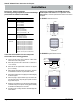
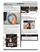
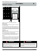
Figure 10. C-View Residential Power Vent Module
Left-sideView
Power Vent
Speed Control
Power Vent
Speed Control
Right-sideView
LED Indicator
Fuse
110V Power Supply
Wall Switch
6 - conductor
communication
cable
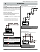
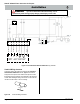
Figure 11. (Remote Switch Wire connection)
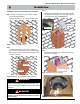
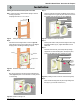
Figure 8. (Fireplace to Control Panel Harness)