
Owner`s manual

Page 16
R520-ST & R620-ST Power Vent Indoor Gas Fireplace
Part No. XG0773 - 032211
Installation
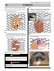
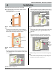
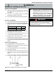
Step 8.
Install the Power Vent Power / communication harness. Hold the
Power Vent in close proximity of the assembled Rough-in Kit,
and plug in the Power Vent communication / Power Cord. (Note
the direction and orientation of the pins inside the Power Vent
connector, snap together). (Figure 6f).
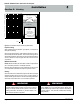
Step 9.
Install the Power Vent. Place the Power Vent into the Rough-in
frame, aligning the Power Vent into nal position. Ensure the
Harness is placed down in the Rough-in box when placing the
Power Vent. (Secure the Power Vent in Place with the supplied
hardware).
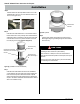
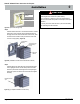
Figure 6f. (Installation of Power Vent communication harness)
TOP of Power Vent,
(Note Quantity of
louvers).
Note louver
direction
Tightened hardware,
4-pcs.
Communication
Harness.
Figure 6g. (Completed Installation of Power Vent)
Figure 6e. (Assembled Rough-in Kit)
Tightened hardware, 6-pcs.
Installed Power Vent
Connector
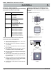
CAUTION!
Vent terminations can be very hot. The termination is to be
installed higher than 7 feet above a public walkway.
Do not obstruct, or attempt to conceal, the vent termination.
These actions will affect the operation of the replace, and may be
hazardous.
In heavy snow areas, take extra care to prevent snow buildup
from obstructing the vent termination.