
Owner`s manual

Page 15
R520-ST & R620-ST Power Vent Indoor Gas Fireplace
Part No. XG0773 - 032211
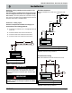
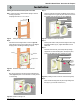
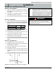
Figure 6. Framing the Opening for Power Vent
14 1/2”
14
1/2”
(Opening)
(Opening)
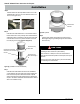
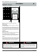
Step 2.
Insert the Power Vent Rough-in Box as shown in Figure 6a.
Fasten the Box securely in place with Screws or nails, Figure
6a. Apply exterior sheathing and nishing if required.
Step 3.
Next, remove the bottom collar and conduit mounting frame as
shown Figure 6b. (Place removed hardware in a handy location
for re-assembly).
Figure 6a. Orientation, Placing the Power Vent Inner Box
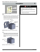
Framing
Rough-in Frame
Fasteners
Figure 6b. Installation of Rough-in Kit
Installation
Installing the external wall mounted power vent module
Step 1. Construct a frame for the termination opening to meet the
following requirements:
■ Opening Size must be: 14 1/2" x 14 1/2".
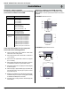
Figure 6c. Installation of Power Vent Conduit
Power Vent Conduit
Strain Relief
Nut
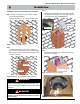
Step 4.
Insert the conduit from the Power Vent Module into the rough-in
frame through the two top right entry holes. Remove the nut from
the supplied strain relief and place as shown, Figure 6c.
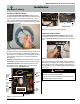
Strain Relief
Figure 6d. (Installing Conduit connector & conduit mounting frame)
Power Vent Conduit
Strain Relief & tightened nut
Power Vent
Connector
Conduit
mounting
frame
Step 5.
Securely fasten bottom Collar pan into the Rough-in frame using
the existing hardware, (4-pcs). Tighten Strain Relief nut onto
Strain relief.
Step 6.
Pull Power Vent Connector, (from behind) half-way through
supplied hole in conduit mounting frame, and snap into place,
(notches in two plastic wing clips. Orientation not critical).
Tightened hardware, 4-pcs.
Step 7.
Fasten Conduit mounting frame into place using existing hard-
ware, (6-pcs). (Coil conduit in behind cover.)