
Owner`s manual

Page 13
R520-ST & R620-ST Power Vent Indoor Gas Fireplace
Part No. XG0773 - 032211
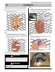
Installation
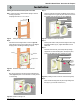
Section 3-2-1: Venting Layout
Selection of components and details of venting lay out
should adhere to the following guidelines:
Ensure there is a minimum run of 2’ of straight pipe before the
power vent.
Ensure the maximum vent run does not exceed 100’.
Ensure the number of 90° elbows does not exceed 6.
Ensure the number of 45° elbows does not exceed 12.
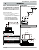
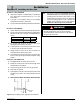
Figure 5. Typical Venting Installations.
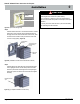
Multi-Elbow Installations
Multi-elbow installations are possible up to a maximum of six 90°
elbows.
Figure 5a. Multi-elbow Venting Installations.
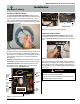
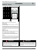
Figure 5b. Downward Venting Installations.
Downward Vertical Venting
Note: The downward vent run must not exceed 6' of vent run.
Max V + H Max Elbows
100’feet six 90
Max V1 + H1 + V2 + H2 + V3 + H3 Max Elbows
100’ feet six 90
WARNING!
All venting material must be sealed with high heat silicone sealant
RV230. All venting material to be Montigo ex pipe, with as few
joints as possible. All joints use MVA vent splice, sealed thoroughly
with silicone.
WARNING!
Montigo will not be held responsible for any water damage
that may occur from not installing the equipment as specied
by this document.
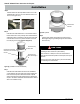
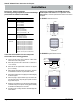
Section 3-2: Installing a Wall Mounted Vertical Exterior Power
Vent (EPVRW)
This section applies to installations where the shortest possible
vent run is through an exterior wall. Refer to Appendix A - Power
Vent locations, to ensure the planned Power vent location is accept-
able. Once the vent location has been established, please refer to the
appropriate section below for installation details.
Max V1 + H1 + D + H2
Max Elbows
40’ feet
six 90
H
V
Elbow 1
Elbow 2
Elbow 3
Elbow 5
Elbow 4
Elbow 6
H3
H2
H1
V1
V2
V3
H2
H1
V
D