
Owner`s manual

Page 11
R520-ST & R620-ST Power Vent Indoor Gas Fireplace
Part No. XG0773 - 032211
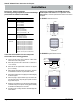
WARNING!
All venting material must be sealed with high heat silicone sealant
RV230. All venting material to be Montigo ex pipe, with as few
joints as possible. All joints use MVA vent splice, sealed thoroughly
with silicone.
WARNING!
Montigo will not be held responsible for any water damage
that may occur from not installing the equipment as specied
by this document.
Installation
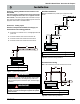
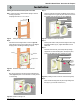
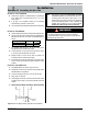
Figure 4. Contruction, Rough-in framing.
14 1/2”
14 1/2”
18”
14 1/2"
14 1/2"
18"
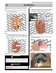
Step 1. Construct a Vertical Chase for the termination opening to
meet the following requirements:
■ Opening Size must be: 14 1/2" x 14 1/2" x 18" Min. height.
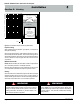
Step 2.
Install the Vent pipe female end up, and 2" to 3" MAX. from
the top of the Constructed Chase. Also, at this point install the
Electrical harness, (EPVH-(10-100) that will communicate with
the Power Vent Module.
Vent Pipe
Vent Chase
Electrical Harness
with Connection
2 to 3” M
AX
Figure 4a. Installation, Vertical Vent pipe. (female end top end).
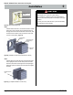
Figure 4b. Installation of Rough-in Kit
Electrical Harness
Power Vent
Rough-in Kit
Electrical Harness
Connector Location
Inset
Step 3.
Install the Power Vent Rough-in Kit. Pull wire harness through
the supplied hole in the bottom corner of the rough-in box, and
snap into the slot provided, (See gure 4b inset).
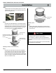
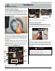
Figure 4c. (Fasten Rough-in Kit to framing)
Install Fasteners around
perimeter of Rough-in Kit
Step 4.
Install fasteners around perimeter of Rough-in Kit. (Holes sup-
plied for ease of installation)
Figure 4d. (Installed Stainless steel cover)
Installing the external roof mounted power vent module