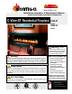
fire feature www.montigo.com Installation Operation & Maintenance Manual Check local codes and read all instructions C-View-ST Residential Fireplace R520-ST Indoor R620-ST Indoor Warning: If the information in these instructions is not followed exactly, a fire or explosion may result causing property damage, personal injury or death.
R520-ST & R620-ST Power Vent Indoor Gas Fireplace Warning: Read this manual before installing, operating or troubleshooting this appliance. Please retain this owner's manual for future reference. Table of Contents Congratulations Section 4: Wiring.................................................................... 17 Safety Alert Key Introduction................................................................................ 3 Models.................................................................
R520-ST & R620-ST Power Vent Indoor Gas Fireplace Introduction Safety Alert Key: • WARNING! Indicates a hazardous situation which, if not avoided could result in death or serious injury. • CAUTION! Indicates a hazardous situation which, if not avoided, could result in minor or moderate injury. • NOTICE: Used to address practices not related to personal injury. • Important: Used to address practices not related to personal injury. INTRODUCTION Congratulations on your purchase of a Montigo Fireplace.
R520-ST & R620-ST Power Vent Indoor Gas Fireplace Installation IMPORTANT MESSAGE: SAVE THESE INSTRUCTIONS The C-View Residential R520-ST & R620-ST Power Vent fireplaces must be installed in accordance with these Instructions. Carefully read all the Instructions in this manual first. Consult the Local Gas Branch to determine the need for a permit prior to starting the installation.
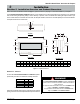
R520-ST & R620-ST Power Vent Indoor Gas Fireplace Installation Section 1: Installation Overview and Product Dimensions Please review the Pre-Installation Checklist on Page 4 for general information on preparing for a successful installation of your fireplace. The C-View Residential R520-ST & R620-ST fireplaces may be installed in any location that maintains proper clearances to air conditioning ducts, electrical wiring and plumbing.
R520-ST & R620-ST Power Vent Indoor Gas Fireplace Installation Section 2: Framing Step 1. You will need to construct a platform in the framing for the fireplace to sit on. To determine how high to build the platform you must determine the how high you would like the bottom edge of your glass viewing area to be. The bottom edge of the glass sits 15 1/8" above the top of the platform. Please note: The top of the platform may not exceed 24" in a room with 8' ceilings.
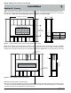
R520-ST & R620-ST Power Vent Indoor Gas Fireplace Installation NOTE: Remember, both sides of the Fireplace require the same quantities of wood, drywall and hardware. Cut the Upper and Lower Horizontal 2 x 4's as shown in Figure 2b. Next, cut the Required quantity of short filler 2x4's under the lower Horizontal. Follow Typical building codes and practices when spacing. Next, cut the Required Left and Right Vertical 2 x 4's as shown in Figure 2b.
R520-ST & R620-ST Power Vent Indoor Gas Fireplace Installation Figure 2c. Montigo supplied RHS 102 required as venting passes through the first adjacent ceiling or wall for horizontal vent runs Page 8 Part No.
R520-ST & R620-ST Power Vent Indoor Gas Fireplace Installation Section 3: Installing the Power Vent Montigo supplies a variety of power venting options. The location of the power vent should be selected and laid out to provide the shortest possible run to an external wall or through the roof. Multi-Elbow Installations Multi-elbow installations are possible up to a maximum of six 90° elbows.
R520-ST & R620-ST Power Vent Indoor Gas Fireplace Installation Section 3-1-2: Venting Components The following venting components and associated Montigo part numbers are available for the EPVRR: A - Termination EPVRR B - Rough-in Frame EPVRRF RFL-1 (12" Section) RFL-2 (24" Section) RFL-3 (36" Section) RFL-4 (48" Section) C - Flex Sections D - Rigid Sections Section 3-1-3: Installation of the EPVRR external roof mounted power vent module.
R520-ST & R620-ST Power Vent Indoor Gas Fireplace Installation Installing the external roof mounted power vent module Step 1. Construct a Vertical Chase for the termination opening to meet the following requirements: Step 3. Install the Power Vent Rough-in Kit. Pull wire harness through the supplied hole in the bottom corner of the rough-in box, and snap into the slot provided, (See figure 4b inset). ■ Opening Size must be: 14 1/2" x 14 1/2" x 18" Min. height.
R520-ST & R620-ST Power Vent Indoor Gas Fireplace Installation Step 5. Install the Power Vent, Roof-top Stainless steel cover over the Installed Rough-in Kit. (You can see the Electrical harness connector in the top right corner). Electrical Harness from Power Vent Stainless Steel Fasteners Figure 4e. Figure 4f. Step 6. Install the Power Vent Module Power / communication harness.
R520-ST & R620-ST Power Vent Indoor Gas Fireplace Installation Section 3-2: Installing a Wall Mounted Vertical Exterior Power Vent (EPVRW) This section applies to installations where the shortest possible vent run is through an exterior wall. Refer to Appendix A - Power Vent locations, to ensure the planned Power vent location is acceptable. Once the vent location has been established, please refer to the appropriate section below for installation details.
R520-ST & R620-ST Power Vent Indoor Gas Fireplace Installation Section 3-2-2: Venting Components The following venting components and associated Montigo part numbers are available for the EPVRW: A - Termination EPVRW B - Rough-in Frame EPVRWF RFL-1 (12" Section) RFL-2 (24" Section) RFL-3 (36" Section) RFL-4 (48" Section) C - Flex Sections D - Rigid Sections REXT - 1 (12" m/f Section) RXT-20 (20" section) REXT - 2 (24" m/f Section) REXT - 3 (36" m/f Section) REXT - 4 (48" m/f Section) E - Elbows REL
R520-ST & R620-ST Power Vent Indoor Gas Fireplace Installation Installing the external wall mounted power vent module Step 1. Construct a frame for the termination opening to meet the following requirements: ■ Opening Size must be: 14 1/2" x 14 1/2". Step 4. Insert the conduit from the Power Vent Module into the rough-in frame through the two top right entry holes. Remove the nut from the supplied strain relief and place as shown, Figure 6c.
R520-ST & R620-ST Power Vent Indoor Gas Fireplace Installation CAUTION! Vent terminations can be very hot. The termination is to be installed higher than 7 feet above a public walkway. Installed Power Vent Connector Do not obstruct, or attempt to conceal, the vent termination. These actions will affect the operation of the fireplace, and may be hazardous. Tightened hardware, 6-pcs. In heavy snow areas, take extra care to prevent snow buildup from obstructing the vent termination. Figure 6e.
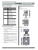
R520-ST & R620-ST Power Vent Indoor Gas Fireplace Installation Section 4: Wiring Installation Of Electrical Supply The C-View Residential R520-ST & R620-ST Fireplaces are supplied with an external electrical Control Panel pre-wired by the factory. The power control box is connected to the fireplace with a 20 foot long 6 conductor cable that will communicate with the fireplace.The control panel should be located in a location that would be accessible when the fireplace in finished.
R520-ST & R620-ST Power Vent Indoor Gas Fireplace Installation If you do not follow these instructions exactly, a fire or explosion may result causing property damage, personal injury or loss of life. WARNING! NC Gas Valve 1 LV Wall Switch 7 8 Gnd Green 6 Brn 5 Blu 4 Red 3 Blk / Wht 2 Wht / Blk Wht / Blk 1 Blk / Wht Pre-purge Time-On delay Post-purge Module NO Combustion Flue Gas Air Switch Switch Fireplace Figure 12.
R520-ST & R620-ST Power Vent Indoor Gas Fireplace Installation Section 5: Installing the Gas line Section 5-1: FUEL CONVERSION Verify that your fireplace is compatible with your available gas type. (Natural Gas or Propane shown by "N" or "L" in your model number If gas type is not compatible, contact your local Montigo representative to purchase a conversion kit. Conversion kits must be installed by a qualified service technician.
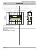
R520-ST & R620-ST Power Vent Indoor Gas Fireplace Installation Section 6: Finishing 20 19 18 17 16 15 14 13 12 11 10 9 8 7 6 5 4 3 2 1 Combustible facing material Start of combustible framing Combustible construction allowed in shaded area Top of fireplace Non-combustible headers supplied by Montigo (may be placed where required for fastening facing) 12 11 10 9 8 7 6 5 4 3 2 1 Glass Figure 16. Combustible mantles and facings.
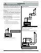
R520-ST & R620-ST Power Vent Indoor Gas Fireplace Installation Section 7: Removing & Installing the Door Removing the doors: The doors are removed in a few simple steps. Follow the steps below to remove the Vertical Door trim, place the Door removal tool, and then remove the door. Replace all the parts in reverse order. Step 3. Hold the Glass Removal Tools firmly, Lift the door upward, into the top door frame, Figure 17c.
R520-ST & R620-ST Power Vent Indoor Gas Fireplace Installation Section 8: Installing the Firestones The C-View Residential R520-ST & R620-ST fireplace have the option of installing the supplied glass Firestones or other optional colored glass media, or cultured rocks. Note: The designer Firestones or cultured rocks cannot cover the burners, doing so produces an undesirable / uneven flame pattern and eventual sooting.
R520-ST & R620-ST Power Vent Indoor Gas Fireplace Operation with Honeywell Electronic Ignition For Your Safety - READ BEFORE LIGHTING: WARNING! If you do not follow these instructions exactly, a fire or explosion may result causing property damage, personal injury or loss of life. A. This appliance is equipped with an ignition system that lights the pilot burner automatically. Do not attempt to light the pilot by hand. B. BEFORE LIGHTING smell all around the appliance area for gas.
R520-ST & R620-ST Power Vent Indoor Gas Fireplace Operation Proflame SIT Electronic Ignition For Your Safety - READ BEFORE LIGHTING: with American Flame Electronic Ignition WARNING! If you do not follow these instructions exactly, a fire or explosion may result causing property damage, personal injury or loss of life. A. This appliance is equipped with an ignition system that lights the pilot burner automatically. Do not attempt to light the pilot by hand. B.
R520-ST & R620-ST Power Vent Indoor Gas Fireplace Maintenance Gas Control Valve (Honeywell HSI) Lighting Instructions See pages 23 and 24. Honeywell (Q3450) Pilot Assembly Pilot Electrical Harness Connector Honeywell Gas Control (SV9501M) Gas Control Connector General Have the fireplace and installation inspected yearly. The inspection must include, but is not limited to, the following: • A visual check of the entire vent system and termination.
R520-ST & R620-ST Power Vent Indoor Gas Fireplace Maintenance Troubleshooting: (Honeywell). Troubleshooting: (SIT - IPI Electronic) 1. Locate the lead to the battery backup, (remove) (Refer to schematic, below) 2. Locate the AC/DC wall transformer, (Unplug connector) (Refer to schematic, below) 1. 2. If your fireplace still does not operate correctly, consult your dealer or the manufacturer. If your fireplace still does not operate correctly, consult your dealer or the manufacturer.
R520-ST & R620-ST Power Vent Indoor Gas Fireplace Appendix A - Power Vent Locations V Horizontal Detail Vertical Detail A = clearance to the termination frame above grade, veranda, porch, deck, or balcony [30 inches (75 cm) minimum] N= B = clearance to door, or sides and top of window, that may be opened [30 inches (75 cm) minimum for appliances.
R520-ST & R620-ST Power Vent Indoor Gas Fireplace Appendix A - Power Vent Locations EPVRR Vertical Power Vent Detail EPVRW Horizontal Power Vent Detail Wall 30”Min. “R” Eaves / Overhang Wall Wall 30”Min. “R” “R” Top View 24” (61cm) Min. “V” 30”Min. “H” & “I” 30”Min. “F” & “G” 30” (75cm) Min. “V” Front View Wall 18” 18” Min. Front View Page 28 Part No.
R520-ST & R620-ST Power Vent Indoor Gas Fireplace Appendix B - Warranty The Warranty The Companies warrants the Montigo Gas Appliance to be free from defects in materials and workmanship at the time of manufacture. On the Montigo fireplace, there is a ten-year warranty on the firebox and its components, a five-year warranty on the main burner and pilot burner, and a one-year warranty on the gas control valve, fibre logs and Power Vent Module.
R520-ST & R620-ST Power Vent Indoor Gas Fireplace Appendix C - State of Massachusetts Amendment (Gas Fireplace / Equipment sold in the State of Massachusetts) 5.08: Modifications to NFPA-54, Chapter 10 (1) Revise NFPA-54 section 10.5.4.
R520-ST & R620-ST Power Vent Indoor Gas Fireplace Notes Part No.
XG0773 - 032211 Canadian Heating Products Inc. Langley, BC V4W 4A1 Montigo Del Ray Corp.