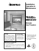
MW38-DV Modular Fireplace Installation Operation & Maintenance MW38-DV Modular Gas Fireplace Warning: Improper installation, adjustment, alteration, service or maintenance can cause injury or property damage. Refer to this manual. For assistance or additional information consult a qualified installer, service agency or the gas supplier. For Your Safety: Do not store or use gasoline or other flammable vapors and liquids in the vicinity of this or any other appliance.
MW38-DV Modular Fireplace Table Of Contents Introduction About the Wildfire 38: Introduction ............................................................................. 2 Installation Installing the Fireplace Shell ......................................... 3 Installing the Gasline ..................................................... 4 The Remote Switch ....................................................... 4 Direct Vent Installation ..................................................
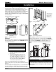
MW38-DV Modular Fireplace Installation Installing The Fireplace Shell The fireplace may be installed in any location that is free of air conditioning ducts, electrical wiring and plumbing. Safety, as well as efficiency of operation, must be considered when selecting the fireplace location. Try to select a location that does not interfere with room traffic, has adequate ventilation, and offers an accessible pathway for Direct Vent installation. Refer to page 4 - Vent Installation for more information.
MW38-DV Modular Fireplace Installation Installing The Gas Line Vent Installation The gas line must be installed before finishing the MW38-DV Fireplace. Natural Gas requires a minimum inlet gas supply pressure of 5.5" W.C. & a manifold pressure of 3.5" W.C. Propane Gas requires a minimum inlet gas supply pressure of 11" W.C. & a manifold pressure of 10" W.C. Provision must also be made for a 1/8" N.P.T.
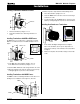
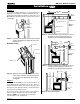
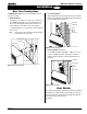
MW38-DV Modular Fireplace Installation Installing Terminations with Built-In Frames termination may not be easily installed from the building's exterior. 11 1. Frame the termination opening to 12" x 12". 2. Fasten the MOSR frame to the interior side of the studs using a minimum of 4 screws. 3. Insert the termination into the MOSR frame as shown here, and attach by screwing through the four pilot holes in the termination. MTO-3F 11 Installing Heat Guards over Terminations 1.
MW38-DV Modular Fireplace Installation Top Vent Top Vent Venting Runs Before you install any venting, you must determine whether the venting run will be acceptable. Unacceptable venting can affect the fireplace's combustion. The Venting Graph Measure the vertical height from the fireplace hearth to the centre of the termination and the horizontal run from the from the fireplace flue collar to the wall flange of the termination. Plot on the Venting Graph (Fig. 9) with an 'X'.
MW38-DV Modular Fireplace Installation Top Vent Example 1: 150" max. 30" max. For our shortest venting configuration use components A and F (see Figure 9a). This configuration is suitable for installations where the fireplace backs directly against 4" stud wall. For deeper walls, use an MEL-90FM elbow and an EXT-18 extension, which can be cut to the required length. Heat Shield Termination Solid Sections Termination Exterior Wall Heat Shield Flex Section MEL-90F/F Elbow Hearth Figure 9a.
MW38-DV Modular Fireplace Installation Top Vent Installation Of Vertical Vent DV Vertical Terminations must be installed: • minimum 2' (two feet) above the highest point where vent passes through the roof. • minimum 6' (six feet) from a mechanical air inlet • minimum 3' (three feet) from a parapet wall. Maximum vent height is 35 feet above fireplace. Note: Flame characteristics will change if the maximum vent height is used.
MW38-DV Modular Fireplace Installation Rear Vent Rear Vent Venting Runs The MD38-DV Rear Vent has three possible installations which do not require vertical lift: 1. Straight Installation. The height from the hearth to the center of the termination is 28 ¾". MD38-DV Rear Vent versions are supplied with an 18" extension pipe (EXT-18) with female/female connections. For shorter installations, cut the EXT-18 to the desired length. 2. 45° Corner Installation.
MW38-DV Modular Fireplace Installation B. Multi-Elbow Installations For more diffiicult installation situations, the MW38-DV Rear Vent may be installed with two - 90° elbows and up to 15' of horizontal run. If using this installation option, you must adhere to the following guidelines: Rear Vent Installation Of Rear Vent DV MW38-DV Rear Vent versions are supplied with an EXT-18 (female/ female) section.
MW38-DV Modular Fireplace Installation Finishing Around the Fireplace Combustible mantels and mouldings may be safely installed over the top and on the front of the fireplace provided that they do not project beyond shaded area shown in Figure 19a. Side wall clearances are 3". Combustible surrounds may be installed with 3" clearance to the side of the fireplace as shown in Figure 19b.
MW38-DV Modular Fireplace Installation Wiring for the optional Fan Kit All 38 Series Modular fireplaces feature an optional fan kit for circulating heat into the living space. Installations in Canada which employ the fans must be electrically grounded in accordance with CSA C22.1 Canadian Electrical Code Part 1 and/or Local Codes.
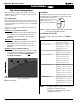
MW38-DV Modular Fireplace Installation Installing the Log Set The MW38-DV is supplied with four (4) fibre logs. Logs "A" and "B" are permanently attached to the log rest, which is pre-installed by the factory. To install the two small logs ("C" and "D"), simply place them onto their mating positions as shown in figure 22a below. When log set is installed it should look like figure 22b. Log 'C' Log 'D' 4. Remove the 4 machine screws that hold the venting plate to the insert. 5.
MW38-DV Modular Fireplace MW38-DV Operation - Model MW38-DV with Continuous Pilot For Your Safety - READ BEFORE LIGHTING: WARNING: If you do not follow these instructions exactly, a fire or explosion may result causing property damage, personal injury or loss of life. A. This appliance has a pilot which must be lighted by hand. When lighting the pilot, follow these instructions exactly. B. BEFORE LIGHTING smell all around the appliance area for gas.
MW38-DV Modular Fireplace MW38-DV-I Operation - Model MW38-DV-I with Honeywell Intermittent Pilot For Your Safety - READ BEFORE LIGHTING: WARNING: If you do not follow these instructions exactly, a fire or explosion may result causing property damage, personal injury or loss of life. A. This appliance is equipped with an ignition system that lights the pilot burner automatically. Do not attempt to light the pilot by hand. B. BEFORE LIGHTING smell all around the appliance area for gas.
MW38-DV Modular Fireplace Operation Lighting Instructions See pages 13 and 14. Burner Adjustment The Wildfire is equipped with an adjustable burner, allowing you to raise or lower the flames. To adjust the flames, locate the black knob marked 'Hi-Lo', in the centre of the gas control valve (See Figure 25). To raise the flame height, turn the black knob (located behind the lower trim) counterclockwise. To lower the flame height, turn clockwise.
MW38-DV Modular Fireplace Maintenance Troubleshooting Gas Control Valve HONEYWELL SV 9500 /SV9600 Troubleshooting Sequence Power Generator Pilot Adjustment Screw NOTE: Before Troubleshooting, Familiarize Yourself With Wall Switch START The Startup And Checkout Procedure. INSET · Turn Gas Supply off · Set thermostat to call for heat Inlet Pressure SV9500/SV9600 is powered (24 VAC nominal) Manifold Pressure Test Connection NO Figure 26. Sit Nova 820 gas valve. YES Pilot Burner Adjustment 1.
MW38-DV Modular Fireplace Warranty The W arranty Warranty The Companies warrants the Montigo Gas Appliance to be free from defects in materials and workmanship at the time of manufacture. On the Montigo, there is a ten-year warranty on the firebox and its components, a five-year warranty on the main burner and pilot burner, and a one-year warranty on the gas control valve and fibre logs. Glass, plated/painted finishes, and refractory lining are exempt.
MW38-DV Modular Fireplace Appendix A - Spare Parts 1 1. Fan Kit () 2. Termination (MTKO/ETKO) 3. Termination Frame (MSR) 4. Termination Frame (MOSR) 2 3 5. Termination Frame - Brick (BSR) 5 4 6. Heat Guard (MTKOG) 7. Wildfire 4-piece Logset 8. 4-Piece Picture Frame Surround (PFS) 9. 3-Piece Picture Frame Surround (PFO) 10. Horizontal Trim Kits 6 11. Door Cover, Square (DF0) 7 12. Door Cover, Arched (DFA) 13. Control Module for Model W38-DVM 14. Control Module for Model W38-DVM-I 15.
MW38-DV Modular Fireplace 16 Appendix B - Termination Locations Page 20 of 19 P/N XG0112
MW38-DV Modular Fireplace XG0112 Rev. 04 - 04/99 P/N XG0112 Canadian Heating Products Inc. Montigo Del Ray Corp.