
Specifications


XG0201 Rev. 02 03/2001
Page 14
M38DV-ST / ME38DV-ST Direct Vented Fireplace
Maintenance
General
n Have the fireplace installation inspected yearly, including a visual
check of the vent system, the burner and the pilot flame. For your
convenience a 1/8" manifold pressure tap is supplied on the gas
valve for a test gauge connection. See Figure 6.
n For Natural Gas this appliance requires a minimum inlet pressure
of 5.5" W.C. and a manifold pressure of 3.5" W.C.
n For Propane Gas this appliance requires a minimum inlet
pressure of 11" W.C. and a manifold pressure of 10" W.C.
n Always keep the fireplace area clear and free of combustible
materials, as well as gasoline and other flammable vapours and
liquids.
n Do not use this appliance if any part has been under water.
Immediately call a qualified service technician to inspect the
appliance and to replace any part of the control system and any
gas control which has been under water.
CAUTION
• Fireplace gas control must be in the “OFF” position and pilot
and main burners extinguished when cleaning appliance with
a vacuum.
• Glass and logs can get very hot. Handle only when cool.
Cleaning
When the fireplace is first activated, there may be some smoking and
a visible film may be left on the glass. This is a normal condition, and
is the result of burningthe protective coatings on new metal.
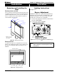
n Glass must be cleaned periodically to remove any film (a normal
bi-product of combustion) which may be visible. Film can easily
be removed by removing the door, as shown on page 12. Handle
the door carefully, and clean it with non-abrasive glass cleaners.
One of the most effective products is Kel Kem.
n Silicone seals on inner door during initial firing will "off gas",
leaving a visual deposit of a white substance on combustion
chamber walls. This can easily be removed by following the steps
described above.
n Use a vacuum cleaner or whisk broom to keep the control
compartment, burner, and firebox free from dust and lint.
n Logs may be cleaned periodically with a vacuum to remove soot.
WARNING:
Do not attempt to clean glass when hot.
Do not clean glass with abrasive materials as any glass
etching may cause premature glass failure.
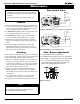
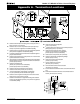
Pilot Burner Adjustment
1. Locate Pilot Adjustment Screw. (See figure 21.)
2. Turn Adjustment Screw until flame is proper size. (See figure 22).
3. After installing or servicing, leak test with a soap solution with main
burner on. Coat pipe and tubing joints, gasket etc. with soap
solution. Bubbles indicate leaks. Tighten any areas where the
bubbles appear until the bubbling stops completely.
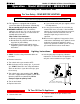
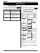
Gas Control Valve
Figure 17a. Sit Nova 820 gas valve for M38DV-ST and ME38DV-ST.
Manifold Pressure
Test Connection
Pilot Adjustment Screw
Inlet
Pressure
Power
Generator
Wall Switch
Figure 17b. Sit 820 gas valve for M38DV-ST (MH).
Manifold Pressure
Test Connection
Pilot Adjustment Screw
Inlet
Pressure
Power
Generator
Wall Switch
Figure 22. Pilot Burner.