
Operating instructions

P/N XG0663
Page 4
M38DV-ST/ME38DV-ST Gas Conversion Kit
Gas Conversion Instructions
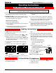
B. Checking the Gas Pressure
17. To check the Inlet and Manifold gas pressures, use a Water
Column Pressure Gauge with 5/16" dia. tubing. Make sure the
gas shut-off valve is closed, then attach the gauge to
the Manifold Pressure Test Connection by loosening the screw
shown in Figure 7. The tubing must be tight in the connection to
prevent gas leaks. Measure the Manifold Pressure and compare
the value against the chart below.
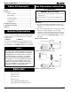
Figure 7. Sit Nova 820 gas valve.
Natural Gas Liquid Propane
Manifold Pressure (min.) 3.5" W.C. 10" W.C.
Inlet Pressure (min.- max.) 5.5" - 14" W.C. 11" - 14" W.C.
" W.C. = inches water column
18. Turn off the fireplace and close the shutoff valve. Remove the
test gauge. Re-tighten the test connection screw to prevent gas
leakage.
19. Repeat the procedure for the Inlet Pressure.
20. If the pressure readings are not within the limits set out, contact
the factory. If the pressure readings are correct, ensure that both
test connection screws are tightened securely, to prevent a gas
leak.
C. Pilot Burner Adjustment
21. Locate the Pilot Adjustment Screw on the gas valve. (See figure
7)
22. Adjust pilot screw to provide properly sized flame. To increase the
flame, turn the screw counterclockwise. To decrease the flame,
turn it clockwise. (The flame should impinge on the thermocouple
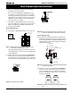
Figure 8. Pilot Burners (Type SIT on left; Type PSE on right).
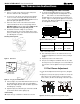
Figure 5. Main Burner.
Main Burner
11. Remove cover plate on both ends of the main (center) burner
and remove main burner tube. (See figure 5)
12. Loosen the set screws at each end of the burner tube. Slide the
sleeves out of each end of the tube and replace them with the
ones from the package marked 'Main Burner Sleeves' in this kit.
(See Inset, Figure 6.) Re-tighten the set screws.
13. Remove the orifices from the orifice holder at each end and
replace them with the new orifices from the package marked
'Main Burner Orifices' in this kit. (See Figure 6.) Make sure the
Orifices are tightened securely to prevent gas leaks.
14. Re-install the main burner, making sure you center the
burner between the two orifices. Ensure that the burner's flame
ports are pointed 90 degrees to the horizontal. Secure the burner
by re-attaching both cover plates.
Checking Your Conversion
15. Leak test using a soap solution with main burner turned on. Coat
pipe and tubing joints, gasket etc. with soap solution. Bubbles
indicate leaks. Tighten any areas where the bubbles appear until
the bubbling stops completely.
16. Light the fireplace pilot, and turn the gas control knob to the ON
position. Ensure all three burners light properly.
6. Re-Assembly
Replace the logs, re-install the door and the door surround.
Figure 6. Changing main burner orifice.
Inset. Remove screw
to release sleeve.
Manifold Pressure
Test Connection
Pilot Adjustment Screw
Inlet
Pressure
Power
Generator
Wall Switch